Escaux Unified Communication Solution
APPLICATION NOTE - ADMINISTRATOR' S GUIDE (SMP 4.8)
Administration Guide: Unified Communication Solution 4.8
Preface
Copyright
Copyright 2007 - 2023 , ESCAUX N.V.
Confidentiality
The information contained in this document should be treated as confidential and should only be shared with ESCAUX N.V. Unified Communication customers. Under no circumstances and under no form should any part of this document be transferred to third parties.
Scope of this Document
The purpose of this document is to allow IT Managers, IT integrators and IP PBX providers to configure and maintain an ESCAUX Unified Communication Solution for their organisation or their customer's organization. This document describes concepts like:
- The ESCAUX SMP interfaces
- Profile, status and callflow definition and configuration
- Dial plan definition, configuration flow and design choices
Version
This document describes the web administration interfaces (SMP) for the version 4.8
The version of this document is v2.2.
Introduction
Glossary
Related to this document, you can find a
glossary with terms and definitions.
Architecture of the unified communication solution
Introduction
The ESCAUX Unified Communication Solution (UCS) offers a unique approach to telephony and unified communications. Using a revolutionary architecture that is simple as well as flexible, scalable and robust, UCS allows you to save time and money when implementing telephony throughout your company. By treating telephony and communications as services, you can guarantee service delivery and discuss service level agreements with the users. The services are managed in a consolidated way, from one central management interface that can be accessed remotely. UCS is a complete and mature solution, incorporating all aspects of a corporate solution, like call centers, operator consoles and the possibility to design your solution to your needs.
Architectural concept
Instead of installing a PABX at your main site, ESCAUX UCS is based on an architecture that rationalises what you use on-site. A site requires an installation for the following reasons:
- Local break-out: an operator delivers a connection to a telephony network physically on your site, so you need a set-up to connect it to.
- Realtime processing: when the users in your organisation use the solution, they will generate a workload for the solution. Ideally, a component of the solution is placed as close to the users as possible to ensure good responsiveness.
Other tasks do not need to be situated on-site for specific reasons: configuration, reporting, and other management tasks do not require realtime processing or a physical connection to an operator. Traditional PABX vendors have integrated them into their servers because these are monolithic and inflexible. Escaux rationalises this and splits off realtime and non-realtime tasks:
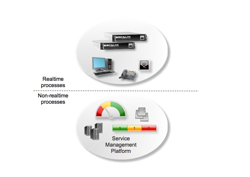
The realtime tasks are executed by Service Operational Points (SOPs). These are appliances that can be installed on-site for connectivity and to be close to the users. If you want, the SOPs can also be installed remotely, as long as the phones and applications can reach them over a network.
Non-realtime tasks are split off in a centralised web interface called the Service Management Point (SMP). The SMP offers amongst others:
- Proactive monitoring: the SMP monitors your SOPs on a regular base and can raise alarms when problems arise.
- Automated backups: the SMP makes nightly backups of each of your SOPs. Even in a complicated multi-site set-up, your backup policy is simple because it has been completely been automated.
- Reporting: you can generate reports about the usage of telephony, the presence of your users and the performance of your reception and call center.
- Management: after logging in, you have access to a web interface to perform all management tasks (add or change users, map your DDIs to extensions, install or define new services, change a welcome message, ...)
Connection between the SOPs and the SMP
When the SOP boots, it will automatically register with the SMP using the SSH protocol. All management and configuration actions are performed at the level of the SMP. The configuration is stored in the SMP database and upon request by the system administrator, the configuration files are encrypted, sent and applied at the level of the SOP.
Getting started
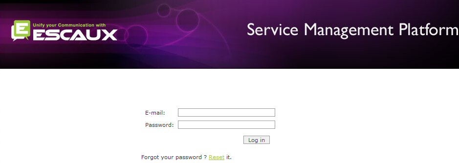
Logging in
Point your web browser to:
https://smp.escaux.com and enter your login and password.
- Login: (your email address)
- Password: (given by ESCAUX)
When you actively start using and configuring your solution, you will have gone through an installation and project management phase. During this phase, our project management team will have done most of the preconfiguring that the solution needs. The solution will be ready to use, ready to make your daily changes, and ready to adapt to your needs if necessary.
Configuration cycle
Because the unified communication solution consists of a configuration part (the SMP) that is separate from the components that will execute your configured services (the SOPs), a configuration change is not immediately active. For that reason, you will use the following cycle when modifying your configuration:
- Make snapshot (optional): if you are making changes that can have a lot of impact, the SMP offers an easy way to make a snapshot of your current configuration. With a few clicks of your mouse, your configuration is safe and can be restored if your changes don't work as expected.
- Change: make the modifications you want. These can be as simple as correcting a spelling mistake in a user's name, or as complicated as developing and configuring a new reception callflow for use.
- Apply changes: with this menu, you can push your configuration changes to the SOPs. The changes are now live in your set-up.
- Test: use the solution to test if the changes work.
- Conclusion: if the changes are correct, your configuration cycle has finished. If they don't work as expected, you can go back and make more changes. In case of problems, you can always restore a snapshot if you have made one.
The SMP offers a global "apply changes" menu item that will apply all changes to all SOPs in your set-up. This may be time consuming if you want to test a number of small changes in a large set-up. For that reason, the SMP provides several shortcuts to apply only the changes to the part of the configuration that have changed. These are mentioned in the respective sections of the SMP configuration menu.
SMP configuration and menus
About this chapter
Introduction
This chapter describes the complete menu structure of the SMP. When you log in on the SMP and select a SOP to work on, you get a menu bar with two lines at the top of your screen:

The remainder of this introduction discusses the notations and common language (visual and textual) of the menus of the SMP.
This chapter uses the following notation to indicate in which kind of set-up certain menus are available or unavailable:
| Menu item |
Service |
Non-clustered SOP |
Clustered SOP |
Cluster level |
Clone level |
| Menu item name |
N/A |
 |
|
Menu item alternative name |
|
These are the columns shown:
- Menu item: this column shows the name of a menu item. For example, in the menu "Apply changes", there is a menu item called "View progress".
- Service: the unified communication solution offers you access to services that you have ordered. Some menu items are specifically targeted at the configuration of one or more services. In that case, this column shows which services will be operated on by selecting that menu item.
- Non-clustered SOP: the mark indicates that this menu item is available in a SOP that is not part of a cluster. For example, when configuring standalone SOPs for a single-site company of maximum around 200 users, this menu item will be shown.
- Clustered SOP: the lack of mark indicates that this menu item is not available in a SOP that is part of a cluster. For example, when configuring one SOP that is part of an active-active redundant set-up, or when configuring one SOP that is part of a large capacity set-up, this menu item will not be shown.
- Clustered level: the alternative name that is specified indicates that this menu item has an alternative name on the cluster level. When configuring a set-up with more than one SOP in a cluster (active-active redundancy or high capacity), you can focus on one SOP or make certain configurations on the whole cluster at once. When working in the cluster level view, this notation indicates that the menu item will exist but with an alternative name.
- Clone level: when you select a clone of an active SOP configured in active-standby redundancy mode, the menu will be drastically reduced. You cannot configure a clone SOP, because its configuration is a copy of the active SOP's configuration. That's why most menus are disabled when you have selected a clone of an active SOP. Some status menu options are available and so is the top bar to switch view to the network, the cluster level or to another SOP.
Different SMP users can have different levels of access. A higher access level has all the rights of a lower level. The following levels exist:
- user: an end user, can only access his own records.
- readonly: Can view but not change all day-to-day administration data (internal directory, phones etc.)
- operator: for simple day-to-day administration, can manage attribution of phones and monitor the system.
- poweroperator: for more advanced day-to-day administration, can manage resources, in addition to what an operator can.
- admin: for service creation, can manage callflows and routing but cannot install modules, in addition to what a poweroperator can.
- poweradmin: has a complete access on the SOPs he owns.
- smpadmin: has a complete access on all SOPs of the SMP.
So, not all menu functions described in this document may be available for you. This depends on your access level. The minimal required access level for each function is indicated below:
| Function |
Required Level |
| Apply Changes |
operator |
| Users (view only) |
readonly |
| Users |
operator |
| Internal Directory (view only) |
readonly |
| Internal Directory |
operator |
| Profiles |
admin |
| Statuses |
admin |
| Callflows |
admin |
| Global Parameters (view only) |
admin |
| Global Parameters |
admin |
| Routes |
admin |
| Media Links |
admin |
| Incoming Number Mapping |
readonly |
| Incoming Number Mapping |
operator |
| Outgoing Number Mapping (view only) |
readonly |
| Outgoing Number Mapping |
operator |
| Phones (view only) |
readonly |
| Phones |
poweroperator |
| Interfaces (view only) |
readonly |
| Interfaces |
poweroperator |
| Queues (view only) |
readonly |
| Queues |
poweroperator |
| Prompts (view only) |
readonly |
| Prompts |
poweroperator |
| Music On Hold (view only) |
readonly |
| Music On Hold |
poweroperator |
| Probes (view only) |
readonly |
| Probes |
poweroperator |
| vSOPs (view only) |
readonly |
| vSOPs |
poweroperator |
| Desktop Applications (view only) |
readonly |
| Desktop Applications |
poweroperator |
| Permissions (view only) |
readonly |
| Permissions |
poweroperator |
| Basic Reporting (view only) |
readonly |
| Basic Reporting |
operator |
| Advanced Reporting (view only) |
readonly |
| Advanced Reporting |
operator |
| Timeslots (view only) |
readonly |
| Timeslots |
operator |
| Pricelist (view only) |
readonly |
| Pricelist |
operator |
| Server Configuration |
poweradmin |
| Install Modules |
poweradmin |
| Define Sites |
admin |
| Define Networks |
admin |
| Action Management |
admin |
| Configuration Snapshot |
admin |
| Manage Template |
poweradmin |
| Manage Public Template |
smpadmin |
| Load Template |
admin |
| Load Public Template |
poweradmin |
| Lock Configuration |
admin |
| System Tasks |
admin |
| View Licenses |
poweroperator |
| Access on all SOPs |
smpadmin |
SMP icons
Throughout the SMP user interface, you will encounter tables that list your users, phones, queues and other components of your unified communication solution. All these tables use the same icons, which results in a consistent user experience. The table below describes these icons.
| Icon |
Explanation |
 \ \ |
Change the item |
 \ \ |
Make a copy of the item, which you can modify before saving |
 \ \ |
Delete the item |
 \ \ |
For some items, you can execute an apply change only for that item. With this option, you can avoid having to execute a full solution-wide apply change when modifying one or a few items only. |
The top bar
Overview
The top bar of the SMP interface has the following items:
| Menu item |
Service |
Non-clustered SOP |
Clustered SOP |
Cluster level |
Clone level |
 Logout Logout |
N/A |
|
|
|
|
 Password Password |
N/A |
|
|
|
|
 Help Help |
N/A |
|
|
|
|
 Network Network |
Consolidated management |
|
|
|
|
 Cluster Cluster |
Consolidated management |
|
|
|
only if clone SOP in a cluster set-up |
 Go to active SOP Go to active SOP |
N/A |
|
|
|
|
 \ \
Version and user info |
N/A |
|
|
|
|
| SOP selection by name |
N/A |
|
|
|
|
| SOP selection by number (SOPkey) |
N/A |
|
|
|
|
 Other admin(s) logged in Other admin(s) logged in |
N/A |
|
|
|
|
 Connected or Connected or  Disconnected Disconnected |
N/A |
|
|
|
|
 Locked Locked |
N/A |
|
|
|
|
Most items can be seen in any configuration. There are a few exceptions:
- The button that redirects you to the cluster level is hidden when your set-up doesn't have a cluster, or when you already are at the cluster level.
- The button that redirects you to the active SOP in an active-standby set-up is only available when you have selected a clone SOP.
The following sections discuss these menu items one by one.
Logout

Navigate to:
The logout button logs you out of the SMP interface and ends your SMP session.
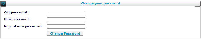
Password
Navigate to:
The password button allows you to change your password. You will be prompted to input your old password, your new password and then your new password again as confirmation:
Help
Navigate to:
The help button opens another browser window with the customer documentation portal:
Network
Navigate to:
The network button takes you to the network overview of the set-up of your unified communication solution where you can quickly view all of your SOPs and choose between any of them, their clones and the cluster level. An overview of a network including all these possibilities would look like this:
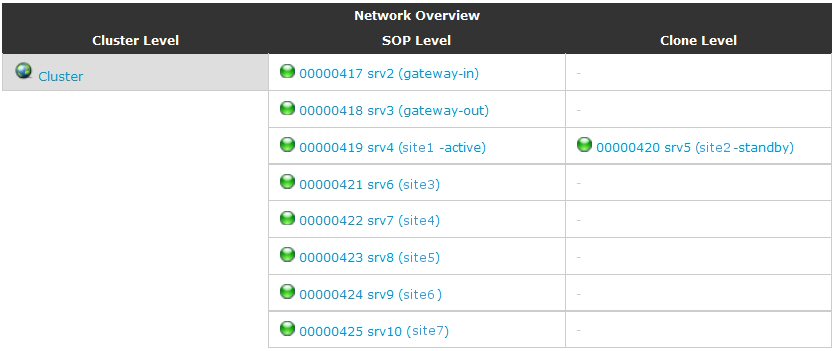
There are three columns:
- Cluster level: The leftmost column shows only one entry for the cluster level. Clicking on this item will bring you up to the level where you can edit the cluster level configuration of your set-up, like the user and callflow management. More details about this level can be found below in the description of the cluster button.
- Cluster SOPs: The middle column shows all the main SOPs in your cluster. One appliance can be dedicated to a site, can be shared by more than one site or can be part of a multi-SOP set-up for a large site. When purchasing your unified communication set-up or when extending your existing set-up with additional SOPs, the sales and customer services organisations discusses the configuration of each SOP with you to guarantee that the set-up of the SOPs corresponds exactly to your needs.
- Clone SOPs The rightmost column shows the clone SOPs for every SOP that is configured in active-standby redundancy mode. After clicking on one of these clone SOPs, the SMP limits the actions that you are allowed to take on the clone SOP. The reason for this is that the configuration of the active SOP will be copied to this clone SOP: all configuration should be done on the active SOP. Yet, the SMP offers you to check the status of the machine and other components related to it. The top bar of the SMP menu adds a special icon to go to the active SOPs, as shown in the list below that lists the limited status capabilities of clone SOP management in the SMP:
Cluster
Navigate to:
The cluster button switches you to the cluster level. This level allows you to configure parts that are shared between all the SOP of the cluster, like:
- user management
- profiles, statuses, call flows
- dial plan and phone number mapping onto extensions
- call queues
- advanced reporting
The section between the top menu buttons and the SOP selection boxes shows your e-mail address as login information and the SMP version. The SMP machine Server name is hidden behind this text, the only way to get it is to put the mouse cursor on the text.
Selecting your SOP by searching
Especially if you have access on many SOPs, the SOP search box may be the quickest way to select a SOP:
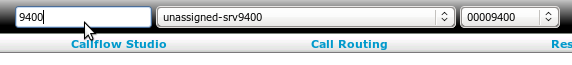
By to typing part of the SOP name or key in the search box, the dropdows will be filtered accordingly.
Pressing enter will immediately switch to the first SOP matching your search text.
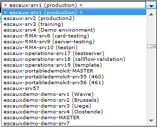
Selecting your SOP by name
You can select which SOP to work on using a drop down menu showing the names of all the SOPs that are accessible to you. The screenshot below shows an example:
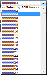
Selecting your SOP by SOP key
You can select which SOP to work on using a drop down menu showing the keys of all the SOPs that are accessible to you. The screenshot below shows an example:
Indicator "Other admin(s) logged in"
When other administrators are logged in on the SOP you have selected, the SMP shows an indicator in the top bar. If you hover your mouse over it, your browser will show you a pop-up tooltip that indicates which other administrator is logged in.
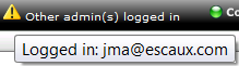
Make sure you discuss with the other administrator before applying any changes. If both you and the other administrator want to modify the configuration at the same time, an apply change may include changes by the other administrator that you did not anticipate or vice versa.
Indicator "Connected" or "Disconnected"
This indicator shows whether you have a connection to the SOP from the SMP. The two options look like this:
If you unexpectedly get a disconnected indicator, check whether your SOP is operational and if your connection to the Internet from the network of the SOP works fine.
Indicator "Locked"
If you have locked your configuration, the following indicator will be shown on the right hand side of the top bar:
You can unlock the configuration using the same menu item used for locking the configuration:
Navigate to: Advanced > Lock Configuration
Overview
This menu of the SMP interface has the following items:
| Menu item |
Minimal Access Level |
Service |
Non-clustered SOP |
Clustered SOP |
Cluster level |
Clone level: menu unavailable |
| Apply changes |
operator |
N/A |
|
Apply SOP changes |
Apply cluster changes |
|
| Check configuration |
operator |
N/A |
|
|
|
|
| View progress |
operator |
N/A |
|
|
|
|
The following sections discuss these menu items one by one.
Introduction
As was described in the architectural description above, the Escaux solution consists of two major parts: the SMP and one or more SOPs. You use the SMP for all configuration of what the SOPs will do. However, when you change the configuration on the SMP, this is not immediately configured on the SOPs. Doing so would mean a performance penalty with every change that you make. Also, it would be dangerous in case you make a mistake: the actual SOP configuration would be modified with an incorrect configuration and problems could arise.
For these reasons, the configuration changes you make in the SMP are not realtime: you can make a number of changes, then decide to apply these changes to the SOPs. This has several advantages:
- The SMP can perform consistency checks before applying the changes. For example, if you have defined phones and software clients but you did not assign these to users, you will be using licenses for no reason. The SMP can check this and give you a warning when it occurs.
- The SMP always has a backup copy of the configuration: even after pushing the new configuration to the SOPs, the SMP still knows what the configuration looks like.
- In case a SOP becomes defective, you can push the configuration from the SMP to a new SOP that replaces the defective one. This is a very fast way to recover from hardware problems.

Since SMP 4.9 the tasks and reports scheduling are also live only after an Apply changes.
This section describes the Apply changes process and the related menu items.
Apply changes
Depending on which level you are editing, the SMP will offer you two options. When configuring one SOP, the menu will show "Apply SOP Changes". When configuring at the cluster level, the menu will show "Apply Cluster Changes".
Navigate to: Apply Changes > Apply SOP Changes
This will update only the changes made to this SOP. Because this is a subtask of the work that "Apply Cluster Changes" does, the explanation of this part can be found in the full explanation of a cluster change below.
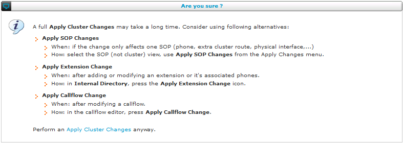
Navigate to: Apply Changes > Apply Cluster Changes
When you select "Apply Cluster Changes", the SMP will update all the SOPs in your cluster. Because this may take a long time in large setups, the SMP will first give you a warning:
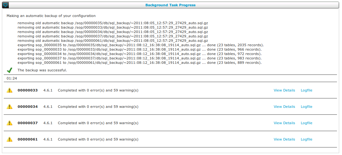
After you have confirmed, the SMP will start a backup of the current configuration. After the backup is complete, the configuration is pushed towards each of the SOPs. Several SOPs will be updated simultaneously. You can follow the progress on the screen:
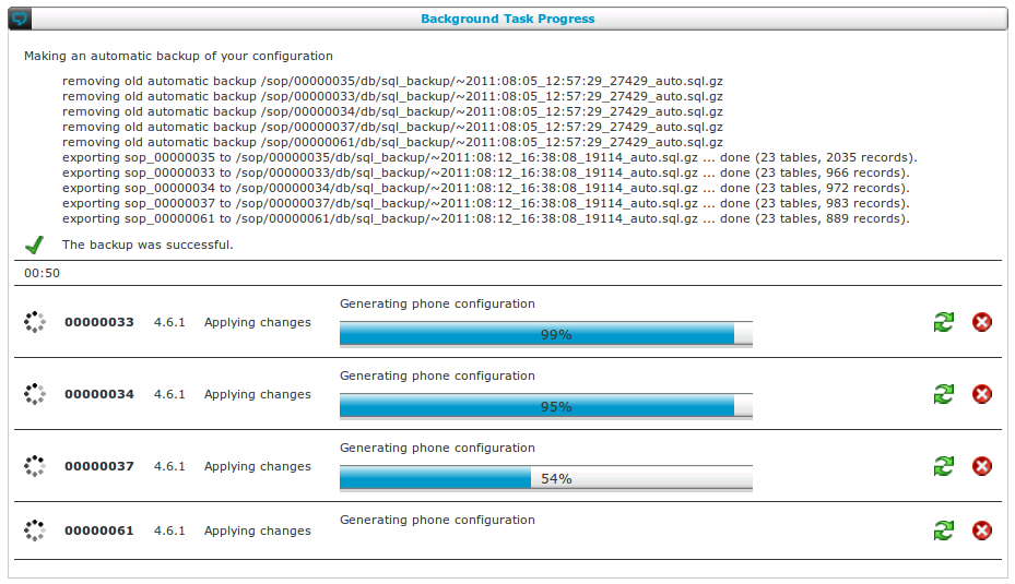
In case the process seems to hang for some reason, you can try to restart it by clicking on the green arrows. Be careful with this and only use it as a last resort, normally it should not be necessary. The background process will be interrupted and started again from the beginning.
If you started apply changes by accident it is usually best to just let it run. However, you have the possibility to abort the process by clicking on the red cross. The background process will be interrupted and not started again.
The apply changes process is a background task, so you can continue browsing the configuration by using the menu. This background task is a component of the SMP called checkd, its version is displayed on the progress page next to the SOP key. To go back to the progress display, use the menu item
Navigate to: Apply Changes > Progress
After the apply changes process has finished, you will get an overview that shows the errors and warnings for each SOP. You can then study the details by using the options on the right:
Checking the configuration
To perform consistency checks on the configuration before applying the changes:
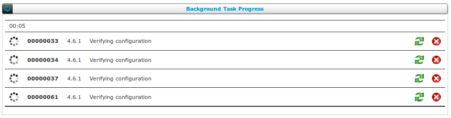
Navigate to: Apply changes > Check configuration
The consistency check starts and shows progress for each of the SOPs in your configuration:
When the configuration has been checked, the SMP shows the results, for example:
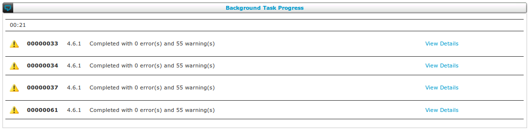
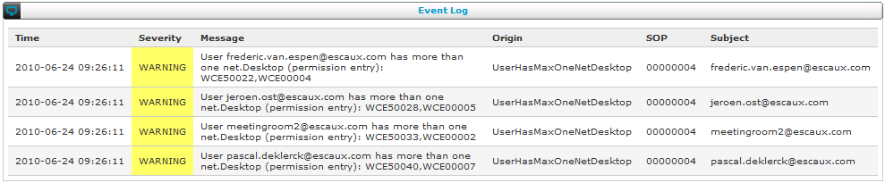
Debug is an internal option that you should only use when advised to do so by our customer services. You can check the details of the problems on one of the SOPs by clicking on "View details". You will get an overview screen as follows:
Progress of the apply changes process
After you have started an apply changes, you can navigate away from the progress display by using the menu. To return to the progress view, use the following menu item:
Navigate to: Apply Changes > Progress
Overview
This menu of the SMP interface has the following items:
| Menu item |
Minimal Access Level |
Service |
Non-clustered SOP |
Clustered SOP |
Cluster level |
Clone level: menu unavailable |
| Users |
operator |
User management |
|
|
|
|
| Internal directory |
operator |
Internal extensions management |
|
|
|
|
The following sections discuss these menu items one by one.
Introduction
Traditionally, each user had at most one phone that had its own phone number or extension to reach it. This standard model is still a very common way to think: the number one question after meeting somebody asks for that person's phone number. However, after the telecommunications revolution of the last decades, it has become very common for users to have more than one phone. With IP telephony, this proliferation continued: it's not unusual to have a fixed phone at home and on your desk in the office, a cell phone or maybe two, a softphone on your PC, and so on. For that reason, we start with a short explanation about the concepts of users, extensions and phones.
- A user is a physical person who controls one or more extensions. On the SMP, users are listed under the "Users" menu item in the "Users" menu.
- An extension is an internal phone number and is also the trigger point for a callflow. A user can control one or more extensions. For example a normal user will only control the behavior of the callflow behind his personal extension, whereas the IT manager will be able to control the behavior of the callflow behind all extensions. On the SMP, extensions are listed under the "Directory" menu item in the "Internal Directory" menu.
- A phone is a physical device that can be called from within a callflow. One extension can be linked to several phones, but one phone can also be triggered by several extensions. There is no one-to-one relationship between an phone and an extension. On the SMP, phones are listed under the "IP Phones" menu item in the "Resources" menu.
Users
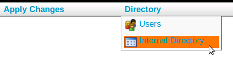
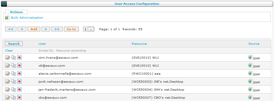
Navigate to: Directory > Users
To manage your users, the SMP presents you with a list view. You can use bulk administration to efficiently manage several users at once, or you can manually edit them, which can be practical for small sites or to quickly make small modifications.
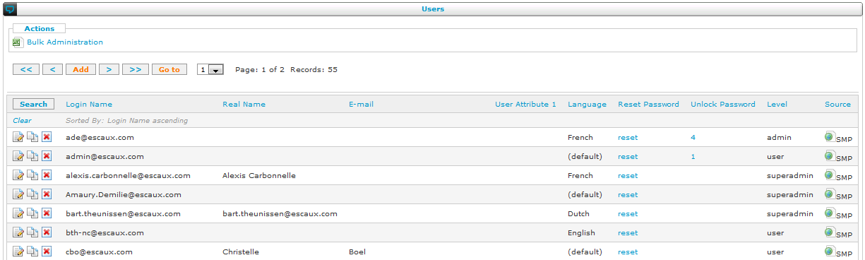
When adding or modifying a user, the SMP will present you with the details screen. Most details are self-explanatory. Remark : Login name should be unique through the whole SMP.
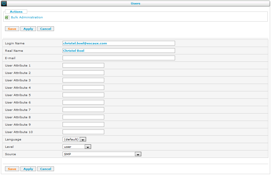
These are a few special fields:
- User Attribute X: these are fields that you can use for your own purposes. They can be synced using LDAP and can be used in callflows to determine the behaviour of the system for that user depending on the value of the attributes.
- Language: the preferred language of the user. This language is available from callflows to determine the behaviour of the system accordingly (play different promts etc.) Can also be used to set the language of a phone.
- Level: the following levels may be available:
- user: when a user logs in on the SMP, he will only be able to change settings related to his user account. This can be limited to one SOP or spread over more than one SOP.
- operator: can manage users and extensions and do apply changes and reporting.
- poweroperator: same as operator but can also manage resources like phones.
- admin: an administrator can manage all configuration of one or more SOPs that he has access to, except for installing modules and changing the network configuration.
- poweradmin: a power admin can do everything an admin can, but he can also install modules, changes the network configuration and accept SSH keys to allow a new or replacement SOP to authenticate with the SMP.
- smpadmin: the administrator of an SMP has poweradmin access to all the SOPs defined on that SMP.
- superadmin: a superadmin has all the rights of an SMP administrator but can also install development versions of modules, actions and resources.
- readonly: same as poweroperator but can only read the configuration. (requires SMP 4.7 or upper).
- Source: when manually entering new users, you can leave this field free. The LDAP synchronisation will use this field to distinguish between synchronised contacts and contacts from other sources.
- Receive Alarms: Enable the user to receive the Backup and Monitoring System alarms via email.
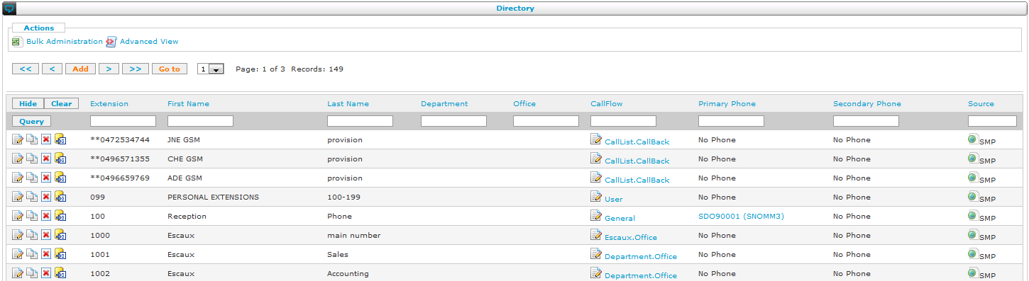
Directory
Navigate to: Directory > Directory
After selecting the directory menu item, you will be presented with an overview of the extensions that the SMP knows.
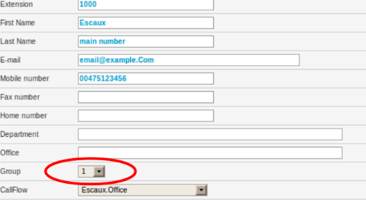
When adding or modifying an extension, the SMP presents you with a detailed view:
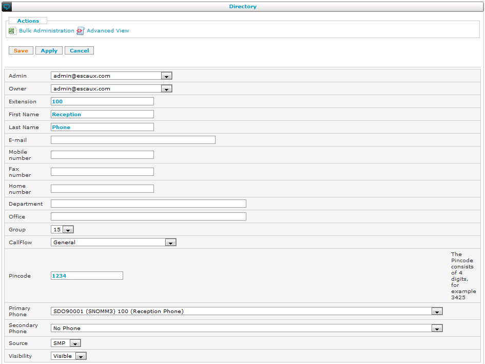
The SOP directory contains the list of all internal extensions. To each
extension we associate the following information:
- Admin: this is the user managing this extension
- Login: this is the user controlling this extension
- Extension: the internal number. Please avoid using an extension from the list 'Predefined extensions' below.
- First Name: first name of the user using this extension
- Last Name: last name of the user using this extension
- E-mail: email address of the user associated to this extension. Voicemail messages will be sent as .wav attachments to this email address. If this email address is undefined, the voicemail-to-email forwarding will not function.
- Mobile Number, Fax Number and Home Number: these numbers can be used throughout the different callflows
- Department: Extra information (whitespace is not allowed)
- Office: Extra information (whitespace is not allowed)
- Group: the group identifier allows you to place users in the same group. A group is useful for example:
- to make all the phones within the same group ring together
- when wanting to perform a call pickup within a group (group pickup)
- CallFlow: the callflow defines the way a call is handled. For more information on callflows see chapter "CallFlow Management"
- Pincode: the pincode is used in various applications, for example voicemail access authentication, DISA access authentication, etc...
- Primary and Secondary Phone: the directory allows to associate 2 devices (Soft Phone, IP Phone, IP/Analog converter, ...) to a particular extension. More devices can be associated via the callflow definition.
 In order to be able to select a phone, the different phones have to be defined via the 'IP Phones' menu item in the 'Resources' menu (see later).
- Source: the database that contains this user's contact information. This field is filled in automatically when synchronising with an external database.
- Visibility: if set to "Hidden", this user is not shown in the client applications.
Predefined extensions
Even if no extensions have been defined through the SMP, a number of extensions are predefined on the Escaux UCS:
Group pickup
A group pick-up by calling
*8 will enable you to pickup an incoming call that is ringing on a phone within your group.
Example: Your colleague is out on a lunch break, and you hear his phone ringing. Instead of walking to his desk to answer the call, pickup your own phone and dial
*8. The call will immediately be transferred to you.
Global pickup
A global pickup by calling
*9 is similar to Group pickup but not limited to your own group.
Example: Your colleague in the office next to you is out on a lunch break, and you hear his phone ringing in the distance. Instead of walking to his desk to answer the call, pickup your own phone and dial
*9. The call will immediately be transfered to you.
This feature can be disabled on your IT administrator's request.
Park
The Park feature enables you or one of your colleagues to continue a call on another phone, without needing to know what phone you'll be using. This is distinctively different to a call transfer as you there have to enter the extension of the phone to forward to.
Example: You receive a call for a colleague who is not at his or her desk. Transfering the call would therefore be quite pointless. Instead, you park the call. You now have time to look for your colleague. When found, you can tell him or her the park extension which was announced when the call was parked. He or she then dials this extension and has the caller on the line.
If the Park feature does not seem to work, please contact the technical support so it can be activated.
Parking a call
Parking an ongoing call can be done by 2 means:
- Composing #700 on the keypad.
- Doing an attended transfer of the call to 700
When done, the Escaux UCS will give you the identifier of the parked call, usually between
701 - 720.
Retrieving a parked call
Retrieving a parked call can be done by dialing the extension which has been announced when the call was parked: usually between
701 - 720.
Voicemail
Your own voicemail can be managed and listened to by calling
8500. The voicemail system will ask your pincode.
If you are not using your own phone you can call
8502. The voicemail system will first ask what extension's voicemail you'd like to access, followed by a request to enter the pincode of this extension's voicemail box.
Other predefined extensions
Other extension ranges are used by the PBX for internal purposes and must not be used in the internal directory. Here is a list of these extensions that complement the above:
| From extension |
To extension |
Used for |
| *001 |
-> *399 |
Callflows |
Move, Add and Change (MAC) of an extension
The Move, Add and Change of an extension is available via an extra icon 'Apply Extension Change' in the Internal Directory interface. This icon located next to the 'Delete' icon of each extension enables to do daily administrative tasks without having to do a full apply changes.
Before using it make sure that you have implemented the following application note:
Extension Move-Add-Change
Changing an existing extension
Navigate to: Directory > Internal Directory > Change icon
Any field appearing of the extension detail window can be modified except the SOP. If you want to change the SOP go to the section
Moving an extension
Always ensure that the primary phone, the secondary phone and the extension are on the same SOP.
Navigate to: Directory > Internal Directory > Apply Extension Change icon
Once completed, reboot the primary or the secondary phones if needed.
Adding a new extension
Navigate to: Directory > Internal Directory > Add
Fill in the required data and ensure that the primary phone, the secondary phone and the extension are on the same SOP.
Navigate to: Directory > Internal Directory > Apply Extension Change icon
Once complete, boot or reboot the primary and secondary phones.
Moving an extension from one SOP to another SOP of the cluster
Navigate to: Directory > Internal Directory
Click on the primary phone and change the SOP of the phone.
Do the same for the secondary phone.
Navigate to: Directory > Internal Directory > Change icon
Change the SOP of the extension.
Navigate to: Directory > Internal Directory > Apply Extension Change icon
Once completed, reboot the primary and secondary phones.
Changing the status of an extension
A user can have different states, for example Office, Forward, Holiday. Every status is linked with a different callflow (a way to handle the call). You can change the status of an extension in different ways. You can do it using netdesktop or calling a specific callflow or on the smp.
Changing the status of an extension using the smp
On the smp:
Navigate to: Directory >Internal Directory
Here we have an overview of all the extensions. Navigate to the Callflow column.
Here you see a change icon and a text (the name of the profile, e.g. User)
Both the text and the icon are click-able and are both different actions.
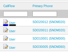
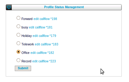
If you want to change the status of an extension Click on the Text (e.g. User). A new page will open.
All the different states for the selected profile will be shown. Here you can just chose your new state and click on the submit button.
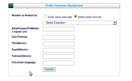
If we click on the change icon in the callflow column we can change the profile parameters for that extension. For example the number where we need to forward to if the extension is in status forward.
Overview
This menu of the SMP interface has the following items:
| Menu item |
Minimal Access Level |
Service |
Non-clustered SOP |
Clustered SOP |
Cluster level |
Clone level: menu unavailable |
| Profiles |
admin |
Profile management |
|
|
|
|
| Statuses |
admin |
Intentional status definition |
|
|
|
|
| Callflows |
admin |
Callflow definition |
|
|
|
|
| Callflow Assignment |
admin |
Callflow assignment |
|
|
|
|
| Callflows - Technical View |
admin |
N/A |
|
|
|
|
| Global Parameters |
admin |
Global parameter management |
|
|
|
|
The following sections discuss these menu items one by one.
Introduction
A fixed phone is much more cost efficient than a GSM. But you can only use it when you are at your desk. To overcome this limitation, the unified communication solution has a system of intentional presence that allows you to instruct the solution on how to treat your calls. Most employees find themselves in a few clearly defined situations for most of their time: they are either at their desk, or in a meeting (possibly out of the office), or on holiday. Some may add teleworking or other states, too. The solution works in the same way as your employees: they can select their status and the solution will react accordingly.
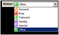
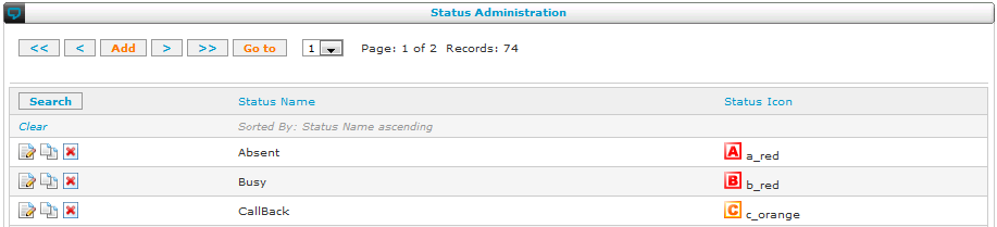
A standard template offers frequently used statuses and user profiles for your convenience: you can just indicate which user has which profile and he automatically has the right choice of statuses. This template includes a director-secretary situation. The screenshot above shows a list of statuses that one employee can choose. If necessary, other profiles and statuses can be defined as well. This is done in the Callflow Studio menu.
Three parameters determine what will happen with a call:
- Profile: a director with a secretary will require different behaviour than a sales person or a regular employee.
- Status: the behaviour will be different when you are working at your desk than when you're in a meeting.
- Callflow: the actual description of the scenario.
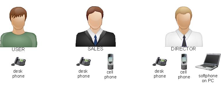
Let's illustrate this with a simplified example. Suppose our company has three types of users:
- standard employees who work in the office, but who have a meeting sometimes
- sales people who are sometimes in the office, sometimes in a meeting, and sometimes on the road
- directors who are sometimes in the office, sometimes in a meeting, sometimes on the road and sometimes working remotely (from home or from a hotel when travelling).
The case of the standard employee is easy: his desk phone is his only phone. When he's unavailable, he can forward his calls to the voicemail. Sales people can also forward their calls that arrive at the office, to their cell phones. Directors have a secretary who answer their calls when he's in a meeting. When he's working remotely, his calls will be forwarded to a softphone that's installed on his PC. The overview is thus as follows:
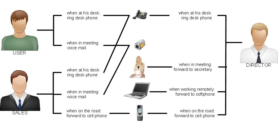
The configuration will thus have three profiles, four statuses and five callflows.
Profiles
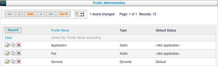
Navigate to: Callflow Studio > Profiles
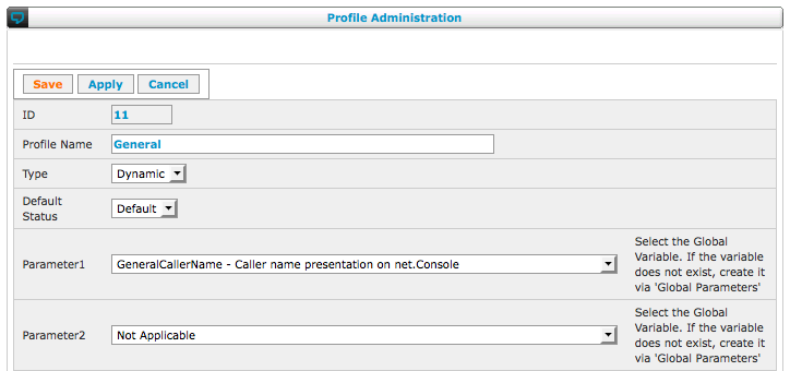
Users within an organization can be categorized into different 'roles' or profiles. Examples are a standard office worker, a helpdesk agent, a director, a receptionist, ... As the administrator you are able to create, modify or remove profiles. This is done via the "Profile Definition" menu item in the "CallfFlow Definition" menu.
Besides the name, number etc of a user you can define custom attributes or
profile parameters. For example a director may have a secretary for which you want to store the number. This would be a profile parameter
SecretaryExtension. Some profile parameters are only relevant for some profiles. E.g. a regular worker may not have a secretary.
Profile parameters are first created using the 'Global Parameters' as explained later in this document.
Up to 42 parameters can be assigned in a profile. To assign a profile parameter to a profile, you pick any free slot and select the parameter from the droplist as shown in the following screenshot:
Dynamic and Static Profile
A dynamic profile allows the user to change his status and his profile parameters (for instance by using net.Desktop). In a static profile the status and the profile parameters are fixed by the administrator and can only be changed on the SMP.
For each dynamic profile, a default status must be chosen. This default status is used to set the initial status of a newly created extension with a dynamic profile or when the profile of an extension is changed to a dynamic profile.
Note that every profile must either be declared as static or as dynamic. A warning will be shown for any dynamic profile that has no default status set. You will not be able to assign such profile to an extension.
Dynamic profiles are usually configured with a STARTDYNAMICAPPLICATION (application selector) and Static profiles a STARTAPPLICATION, although not mandatory. When STARTDYNAMICAPPLICATION is running it receives data directly from the SOP database. STARTDYNAMICAPPLICATION is also required to be able to change the status which is also stored on the SOP.
STARTAPPLICATION doesn't get profile parameters from SOP Database but only uses informations in configuration files generated by Apply Changes.
Pros and cons of Dynamic profiles vs Static profiles:
Dynamic profiles can be managed on the SOP (without smp) using callflows: status and profile parameters are stored on the SOP. Dynamic profiles can be managed by the users themselves using net.Desktop or their phones.
Static profiles can only be managed on the SMP: informations are stored on the SMP and are applied on the SOP.
As a consequence there is a difference for the pre-configuration. Static profiles don't need a connection to the SOP for pre-configuration. On the other side, in order to manage Dynamic profiles a connection to the SOP is mandatory (This will change with SMP 4.10). Note also that changes to Dynamic profiles will cause an immediate operational impact as only a "Submit" is needed in the profile parameters where Static profiles need also an "Apply Changes".
Authoritative source for profile parameters:
- Dynamic Profiles: SOP database. A backup is made by the BMS. SMP database contains a copy only if changes were made on the SMP web interface.
- Static Profiles: SMP database.
Applying Changes to Profile Parameters
Dynamic Profiles: SMP will show data from the SOP database. Changes are saved to the SOP database directly, and a copy to the SMP database.
Static Profiles: Parameters are only saved to the SMP database, an Apply Changes is needed.
STARTDYNAMICAPPLICATION reads parameters in SOP Database, STARTAPPLICATION only uses configuration files generated by Apply changes.
How to save changes?
| STARTDYNAMICAPPLICATION |
Dynamic Profile |
Submit |
| STARTDYNAMICAPPLICATION |
Static Profile |
Submit + Apply Changes |
| STARTAPPLICATION |
Dynamic Profile |
Submit + Apply Changes |
| STARTAPPLICATION |
Static Profile |
Submit + Apply Changes |
Incorrect Profiles
Dynamic profiles without a default status are incorrect profiles and cannot be assigned to a user (current extensions are not impacted). There are two possibilities to correct it.
- The profile is a static one and does not need a default status: change the profile to static
- The type of the profile is correct: set the default status of the profile.
Profile Documentation
It is possible to attach a documentation page to a profile. End-users can then consult this page to understand statuses and profile parameters of a profile. Different profiles can use the same documentation page.
The current version of the SMP does not allow an administrator to create it's own profile documentation pages. Pre-made documentation pages are provided by ESCAUX.
If you have many parameters in a profile, a simple long list may become overwhelming for the end user. Both net.Desktop and the SMP web interface are able to display the profile parameters for a user in a hierarchically structured form with tabs, titles and subtitles.
To define the structure, click on the profile name in the profile management list view.
Navigate to: Callflow Studio > Profiles
You will start on the root level.
Clicking "Add" will create a form element at that level. You can give it a label (the text to display) and select either a profile parameter or "CATEGORY". The latter will create a sub-level in which you can create other elements.
The "order" is a number that can be used to define the order in which the elements should appear.
When you have created a sub-level, you can drill down to it and start creating elements on that level. Use "Go up a level" to go back to the previous level.
When you have created all your elements, you can use "Preview" to see how it will look like to the end users. Use "Edit" to go back to edit mode.
Statuses
Navigate to: Callflow Studio > Statuses
The next step requires some social engineering to be done by the administrator.
- Identify the different statuses for each possible profile: Office, Telework, Holiday, LoggedIn, LoggedOut, Open, Close, etc...
- Define each of these statuses in the status table
Callflows
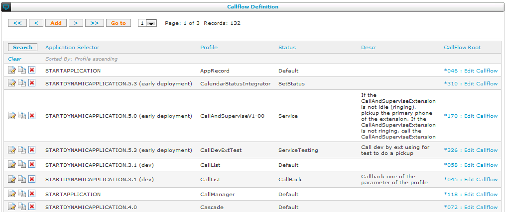
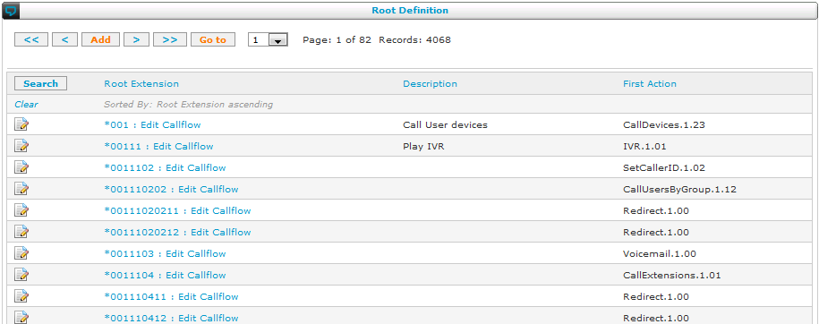
Navigate to: Callflow Studio > Callflows
Call flows are identified by an identifier called the root extension, or root. The root has the form:
There are 999 available callflows, as *000 is reserved. By navigating to the menu above, you can view all the root extensions that are already defined:
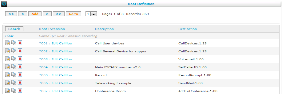
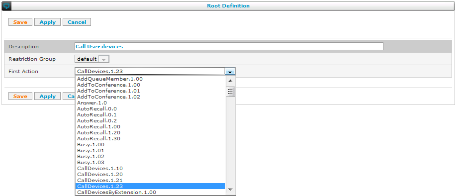
When you define a new callflow, the SMP asks you for the new root extension, a description and the first action that the callflow should execute:

After creating a new callflow, or to edit an existing one, click on the link "Edit Callflow". Doing so will open the Callflow Studio, a visual editing tool that helps you in writing out your scenario.
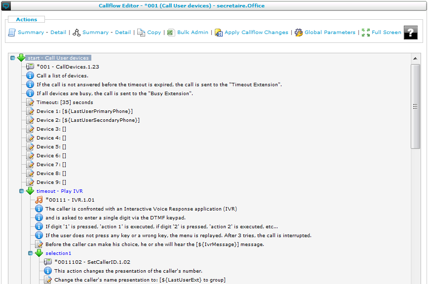
The Callflow Studio offers you the following buttons to guide you while editing your callflows:
-
 \: The option Summary shows each action on one line, with the parameters between parentheses. This gives a clear overview of a callflow for advanced users. The option Detail shows each action with a description and a full list of parameters. This option is practical when you are not fully familiar with the details of all actions yet.
-
 \: The option Summary shows a graph of the callflow with the name of each action as a description. The option Detail shows a graph with more explanation for each action. Both are easy to understand visual representations of your callflow.
- \: With this button, you can copy a callflow to the same or to another SOP.
-
 \: With this button, you can export or import the current callflow to/from a CSV file.
- \: This version of apply change will apply the changes to this callflow only, leaving the rest of the configuration on the SOPs intact. This allows you to quickly test and debug your callflows without having to wait for a full apply change of your cluster.
-
 \: Switches quickly to a view of the global parameters defined in your configuration.
-
 \: Opens another browser tab or window with a full-window view of the callflow studio without menu bars. On smaller screens, this works more efficiently.
To define a callflow, you build a sequence of actions. An action is represented by means of:
- Action Start: (
 \) this is a green arrow pointing to the right (closed view) or pointing down (expanded view). Simply clicking on the (+) or (-) next to the arrow switches between 'closed' or 'expanded' view.
- Action Name: (
 \) this is the root or branch extension (*001, *0010202, ...) followed by the action name
- Action Info: (
 \) this describes the behavior of a particular action
- Action Parameter: (
 \) the value of the action parameters can be modified simply by clicking on them
An action always consists of 1 entry point and 1 or several exit points. Each entry and exit point is uniquely identified by a special extension (*xxxxxx):
In order to create a new action, first 'left-click' on the action start (green arrow) and then 'right-click' to bring up the list of exit extensions.
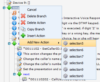
When selecting an exit extension, a pop-up screen will appear asking you to select the next action linked to this exit extension:
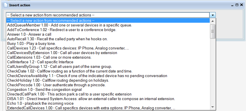
After having selected the action of your choice, a new pop-up screen appears asking you to fill out the different parameter values. Fill out the different parameter values and press submit:
Assigning callflows
Navigate to: Callflow Studio > Assign Callflow
The actual definition of a callflow takes place by selecting the "CallFlow Definition" menu item from the "CallFlow" menu. This opens the CallFlow table:
The definition of a CallFlow requires the administrator to enter the following information:
- Profile: a CallFlow is a combination of a profile and a status
- Status: a CallFlow is a combination of a profile and a status
- Description: add your own description
- CallFlow Root: select the CallFlow root associated with the CallFlow. In the example below, root '*003' is selected.
Technical view of callflows
Navigate to: Callflow Studio > Technical View
The technical view is an advanced way to edit call flows. When you open the technical view, you get not only the root call flows but also each of the call flow steps that follow it:
When you select one of the steps, you can select which action should run. The technical view offers you the freedom to choose an action that is not the default version. This option should only be used in case of emergency, when you know that the default version contains a bug that is fixed in another version.
Global parameters
Navigate to: Callflow Studio > Global Parameters
When you are defining your callflows, parameters make it easy to reuse the same callflow for different situations. In the unified communication solution, parameters are global and can be accessed by all of your callflows. Examples are company's receptionist extension, opening hours, holidays, and so on. The global parameters can be defined in this part of the SMP.
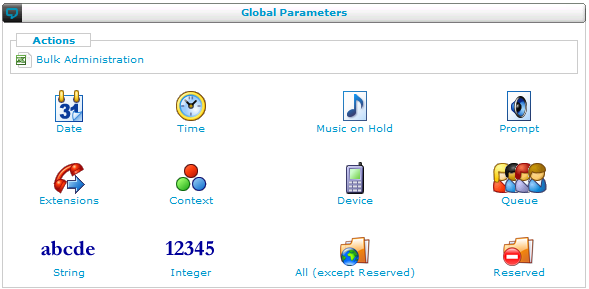
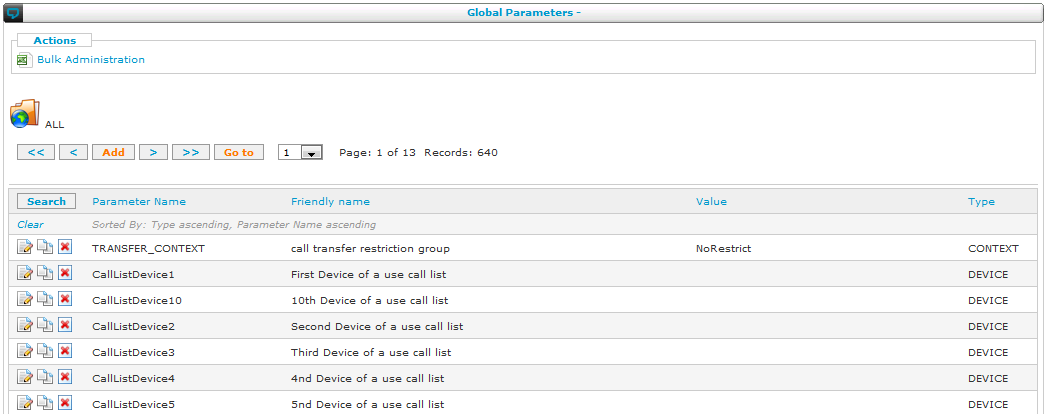
When navigating to the global parameters part, you are first prompted with a selection of global parameter types. After selecting one of the types, the SMP shows you the list of global parameters of that type:
The main purpose of the global parameters is to parametrise a callflow. A global parameter can either be a constant (the parameter is constant for every user extension) or a variable (the parameter can vary from a user extension to another). For example, a global parameter that specifies the time-out when nobody answers the phone can vary for every user. On the other hand, the extension of the company's receptionist is a constant for all the user extensions. The fall back extension which is used in a callflow when a user is busy or does not answer varies from a user extension to another. As a result, this 'fall back extension' and the time-out global parameters must be a variables, but the reception extension is a constant.
If a global parameter is a variable, the administrator can either let each user define the value of the variable or he can restrict this permission to himself. This corresponds to user variables and admin variables, respectively.
Finally, certain global parameters are predefined in the unified communication solution in order to let the administrator customize callflows depending on characteristics of the call (internal extension of the user (LastUserExt), mobile number of the user (LastUserMobile)...).
Summarising:
A global parameter has a specific
OwnerType:
- AdminConst is a constant for all the users and which is set only by the administrator in the global parameter web interface.
- AdminVar is a variable which can vary from one user to another. The value can only be set by the Administrator in the directory web interface.
- UserVar is a variable which can vary from one user to another. The value can be set either by the administrator either by the customer itself in the directory web interface.
Remark:
ESCAUX Parameters (Not seen in the Global Parameter list) are parameters which are predefined by ESCAUX. The actual value of these parameters change in function of the context of the call.
A Global Parameter has also a type, as shown in the first screen where you have to select one:
- PROMPT: Prompt.
- MOH: Music On Hold (example: default)
- DEVICE: A specific device (example: SDC20001)
- EXTENSION: A specific extension or number (example: 00493454545)
- INTEGER : Used for callerID's (see paragraph below)
- SELECTION-LIST : Used to define a set of possible values for this parameter.
- DATE, TIME, STRING, CONTEXT: (Not used)
- PASSWORD: for sensitive data that should not be displayed
- INTERFACE: an interface like a SIP trunk
Finally, when adding a parameter, the following fields must be filled out:
- Parameter Name: This is the unique name of the parameter.
- Friendly Name: This is a short description of the parameter usage.
- Options: This is a comma separated list of AdminConst parameters (Only used by SELECTION-LIST option)
- Value: This is the value. (Only used by constant)
- Type: (PROMPT/MOG/DEVICE/EXTENSION)
- Owner Type: (AdminConst/AdminVar/UserVar)
- Description: This is a detailed description of the parameter. For example, for PROMPT type, the text of the prompt.
See
here for a complete Owner Type discussion and predefined Global Parameter reference.
Relationship between global parameters and profile
Each user has a profile: the role of the user in the company. In order to assure this role, the user can change key parameters used by his callflows. When the administrator defines a profile in the SMP, he can indicate a set of global parameters which will be visible in the user and administrator web interface.
- UserVar owner type (user variable): the user will be able to change the parameter in the directory web interface.
- AdminVar owner type (administrator variable): only the administrator will be able to change the parameter in the directory web interface. The value will be only shown in the user's directory web interface.
- AdminConst owner type (administrator constant): the constant value indicated in the global parameter web interface by the administrator will only be shown in the user's web directory interface.
Overview
This menu of the SMP interface has the following items:
| Menu item |
Minimal Access Level |
Service |
Non-clustered SOP |
Clustered SOP |
Cluster level |
Clone level: menu unavailable |
| Routes |
admin |
N/A |
|
|
|
|
| Intra-cluster media links |
admin |
N/A |
|
|
|
|
| Extra-cluster routing |
admin |
N/A |
|
|
|
|
| Route Groups & Restriction Groups |
admin |
N/A |
|
|
|
|
| Restriction Group Configuration |
admin |
N/A |
|
|
|
|
| Incoming Number Mapping |
operator |
Map external numbers (DDIs) to internal extensions |
|
|
|
|
| Outgoing Number Mapping |
operator |
Define/hide number presentation per internal extension |
|
|
|
|
The following sections discuss these menu items one by one.
Introduction
When configuring your unified communication set-up, you need to assign phone numbers to users. There are several aspects to this process that are documented in this section:
- Internal extensions: each user will get one or more extension (usually a three number code, but this can be configured to match your requirements) for his phones. Each user can also have one or more phones. These are set up in the resources menu, described in the next section.
- External phone numbers: when you ordered your telephony connection, you received a number of DDIs (Direct Dial-In, also called DID: Direct Inward Dialling). These are the normal phone numbers that users outside your organisation can use to reach you. These need to be assigned to reach an extension (for direct dialling to your internal users) or to reach a root extension (for automated pick-up by a callflow).
- Restrictions: each phone can be restricted for outward calls. For example, one phone can be allowed to make international calls while another is not. Some users may have different phones with different restrictions: for example, if a floor manager has both a fixed phone as well as a cordless one, you could put his cordless phone in a group that only allows internal calls. While on the floor, he can call colleagues. For calls outside of the company, he can use his fixed phone in the quieter environment of his office.
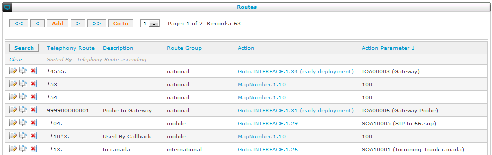
- Routes: to make it easy to restrict phones, you first define routes and route groups. A route maps a phone number pattern (for example, all numbers starting with 0049*) to an interface (a SIM box with a SIM card of a specific provider). These routes are grouped: this and other routes are part of a route group called "mobile".
- Phones and restrictions: a restriction group is a (white) list of allowed route groups for all phones or device resources belonging to this restriction group. For example, one restriction group could contain the route groups "national" and "mobile", but not "international". If a phone belongs to that restriction group, then this phone cannot make international calls.
Phone number patterns
Navigate to: Call Routing > Phone number patterns
The best way to link numbers to routes is to use patterns that will match the wanted numbers to the corresponding routes.
To make patterns, you can use the following special characters:
- X matches any digit from 0-9
- Z matches any digit from 1-9
- N matches any digit from 2-9
- [1237-9] matches any digit or letter in the brackets (in this example, 1,2,3,7,8,9)
- . wildcard, matches one or more characters
- ! wildcard, matches zero or more characters
There are several kinds of patterns that you make using those special characters. Note that every pattern must start with a "_":
| Pattern |
Explications |
Example of matching numbers |
| _0XZ |
Match number starting with a 0, followed by a number from 0 to 9 and a number from 1 to 9 |
001, 042 |
| _112. |
Match any number starting with 112 but with at least one character after the 112 |
1122, 1123 |
| _112! |
Match any number starting with 112 |
112, 1121 |
| _04[6789]Z. |
Match any number starting with 04 then 6,7,8 or 9 and then any number between 1 and 9 |
0482111111, 0467111111 |
Be careful not to use the pattern "_." as it will match everything, including some special extensions used internally.
Route and restriction groups
Navigate to: Call Routing > Route Groups & Restriction Groups
A route group is simply a list of routes grouped together for a certain reason. For example, mobile calls show certain patterns that can be managed in the routes list and they can be grouped together in this list.
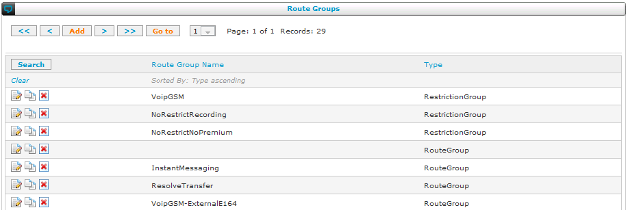
Restriction groups
Navigate to: Call Routing > Restriction Group Configuration
A restriction group is a (white) list of allowed route groups: all users in a restriction group can only call numbers that correspond to routes in the route groups of the restriction group. Setting up the relationship between routes and route groups was done before. This section describes the relationship between route groups and restriction groups.
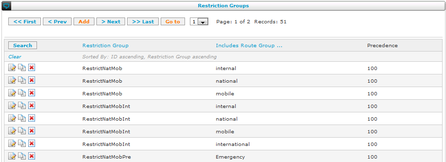
In the above list you can see all the route groups that each restriction group contains. In the screenshot above, we see that the users who are in the restriction group called "RestrictNatMob" can only call internal numbers, national and mobile numbers.
The
Precedence parameter allow to define a priority for each route group in the Restriction Group. This is useful when there are at least two routes that overlap, to ensure that the right route will be selected. Contrary to most routing mechanisms, the
SOP will not necessarily select the route based on the longest matching prefix. Some examples:
- For two routes with the patterns "_04." and "_043.", setting a smaller precedence to the route with the pattern "_043." will ensure that all numbers starting with 043 will use this route and not the other one.
- For two routes with the same pattern but different gateways, sometimes one should be given the priority in a given restrict group. This can be done using a smaller precedence for this route in the given restrict group.
Callflows, voicemail extensions and other predefined voice application are included in the 'default' route group. It is therefore
mandatory to include the route group 'default' in custom Restriction groups.
Restriction Groups and Route Groups are also known as contexts. This nomenclature is sometimes used in interface resource configuration interfaces.
Incoming number mapping
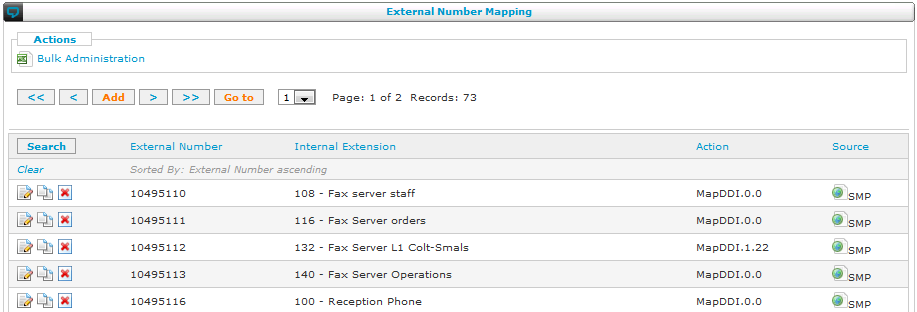
Navigate to: Call Routing > Incoming Number Mapping
Mapping incoming calls comes down to routing the incoming DDI numbers that you received from your phone operator to internal extensions. This can be done using an action, as shown in the list of the incoming number mapping:
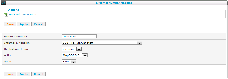
Mapping these numbers onto an internal extension, you can trigger a phone or a root extension (call flow) for automatic answering of calls. The following screenshot shows the detailed view when modifying or adding a mapping:
Outgoing number mapping
Navigate to: Call Routing > Outgoing Number Mapping
When dialling out, you can assign an external number that will be showed to the external contact, or you can choose to hide your number. There are five possibilities that you can select in the SMP:
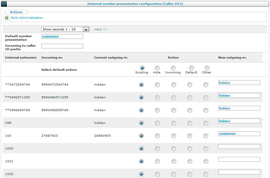
- Existing: reuse the one that is currently configured.
- Hide: don't show any number when dialling out.
- Incoming: use the same number as the one your contacts use to call you directly (DDI).
- Default: use a default number, e.g. the main reception number.
- Other: enter any other number. Of course, limitations apply: you can only use numbers that your operator allows you to use.
Possible issues
When the caller ID configured on the SMP doesn't work, it can result in showing the main number, another number or a hidden number. There are a number of things that might cause this:
If the outgoing routes are configured to not change the Caller ID ("transparent" mode), it will use the internal extension number as Caller ID. This will not work on external trunks. Please verify that this has been correctly configured at
Navigate to: Call routing > Routes
The outgoing routes should either be configured to have the setting "Caller ID policy" set to "Translate" (previously "As set in Global Parameters").
The telephony operator overwrites your changes
If your telephony operator was asked to ignore the caller ID sent by the PBX and set a specific (or hidden) number, you will not be able to set a caller ID. Please contact your telephony operator
The value is not in the syntax required by the Telephony Operator
Quite often, the caller ID will be the national number format sent without a prefixed '0'. However, it might be possible that your Telephony Operator requires a different syntax. First try the number without prefixed '0', afterwards with zero. For example: try 27974409 as well as 027974409.
If this fails, please contact your telephony operator in case of doubt.
The value is not permitted
The Caller ID can only be a number which arrives on your circuit. If you try to send an invalid Caller ID, your telephony operator will either hide the number or use the base number of your circuit.
Example: if the only number range which arrives on your SOP is "027974400 -> 027974409" , you will not be permitted to use 036693120 as Caller ID. The Caller ID value must be, in this example, higher than or equal to 027974400 and lower than or equal to 027974409.
Please contact your telephony operator in order to find out which numbers are available.
Hide Caller ID on SIP trunks: CLIR mode
Some SIP providers allow to send the external callerid on the trunk and hide it for the called party. This is useful for billing purposes.
In order to configure that you have to keep an Outgoing number mapping configured for your extensions. The hidden mode can be configured in the
goto.INTERFACE action in the Extra-cluster routing: use "CLIR" mode.
You can also setup an outgoing callflow to activate CLIR mode. That way you can enable CLIR based on the context or only for some extensions. See the
CallInterface documentation: "Caller ID policy" CLIR and "Shared trunk and IMS trunk" section
Overview
This menu of the SMP interface has the following items:
| Menu item |
Minimal Access Level |
Service |
Non-clustered SOP |
Clustered SOP |
Cluster level |
Clone level: menu unavailable |
| IP Phones |
poweroperator |
IP phone management |
|
|
|
|
| Interfaces |
poweroperator |
Voice interfaces management |
|
|
|
|
| Media links |
poweroperator |
N/A |
|
|
|
|
| Site links |
poweroperator |
N/A |
|
|
|
|
| Networks |
poweroperator |
N/A |
|
|
|
|
| Queues |
poweroperator |
Call queuing |
|
|
|
|
Audio Prompts
Global Parameters
File Manager |
poweroperator |
Audio prompts declaration |
|
|
|
|
Music On Hold
Resource Manager
File Manager |
poweroperator |
|
|
|
|
|
| Probes |
poweroperator |
N/A |
|
|
|
|
| vSOPs |
poweroperator |
N/A |
|
|
|
|
| Desktop Applications |
poweroperator |
N/A |
|
|
|
|
| Permissions |
poweroperator |
N/A |
|
|
|
|
The following sections discuss these menu items one by one.
Introduction
Resources are the components that make your unified communication solution come alive: they are standard building blocks that you can use to set up your solution. The solution offers a wide variety of resources for a variety of purposes. The following sections list these one by one.
IP phones
Navigate to: Resources > IP Phones
This is where you add new phones to your set-up. The SMP shows you a list of all the phones defined in your system.
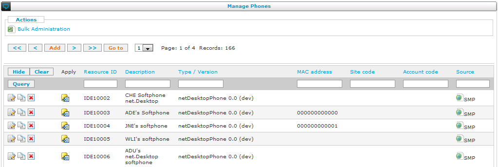
When you add a new phone, you can select the type of phone you want to add:
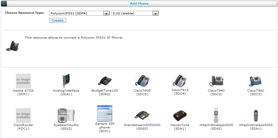
You can enter the parameters for the phone in the next screen. Please consult the
Resource Reference Guide for all the details on the IP Phone configuration parameters.
Interfaces
Navigate to: Resources > Interfaces
This is where you define the interfaces of your set-up. The SMP shows you a list of all the interfaces defined in your system.
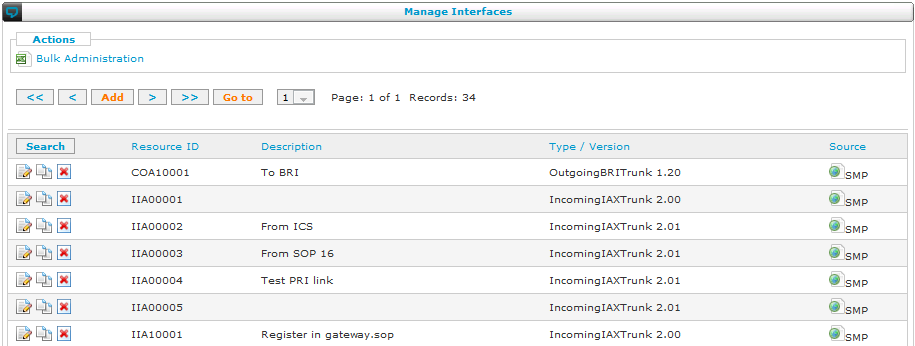
The details of the interface resource are explained in the
resource reference guide.
Queues
Navigate to: Resources > Queues
This is where you add queues to your solution. A queue is a waiting line for phone calls. Incoming calls will be queued as long as nobody is able to answer that call. In the meantime, the caller will hear waiting music. Users can register on the queue to answer calls. The queue will distribute incoming calls according to an algorithm that can be selected by the administrator.
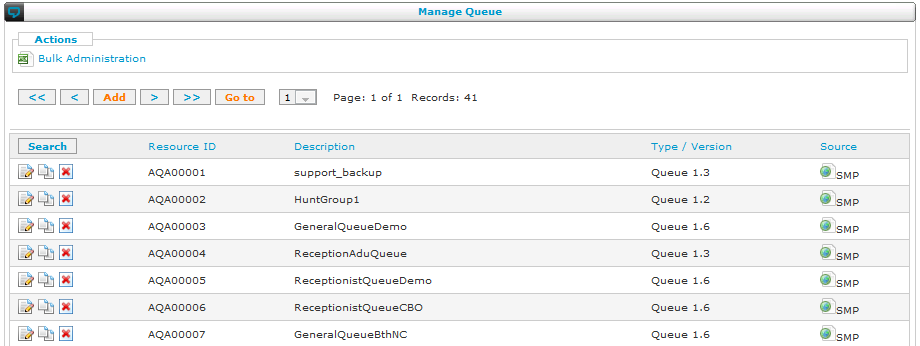
The details of the queue resource are explained in the
resource reference guide.
Audio prompts
Navigate to: Resources > Audio Prompts >Global Paramers
The audio prompts can be managed as global variables. In that case, select the menu item mentioned above, which is equivalent to:
Navigate to: Callflow Studio > Global Parameters > Audio Prompts
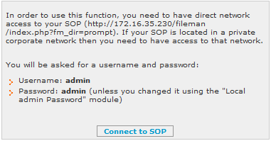
You can also manage the associated files using the file manager:
Navigate to: Resources > Audio Prompts >File Manager
You will get an informational message about access to the SOP:
When uploading your own audio prompts (for example recorded by a professional studio) please respect the following :
- Format : .ul with the option CCITT u-Law format, 8kHz.
- Files should not have any header (for example .wav header)
Music on hold
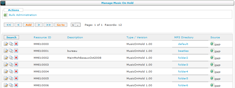
Navigate to: Resources > Music on hold
This is where you define music on hold for your set-up. The SMP shows you a list of all the music on hold tunes defined in your system.
See the
application note Music On Hold for more details.
Probes
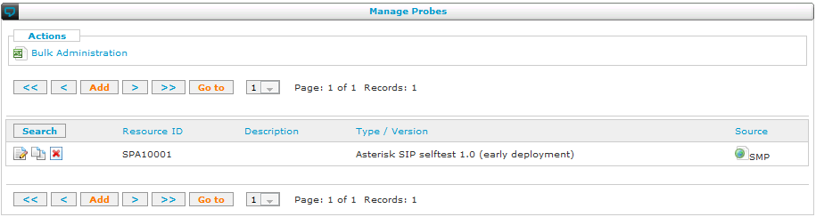
Navigate to: Resources > Probes
This is where you define the probes of your solution. The SMP shows you a list of all the probes defined in your system.
The details of the probe resource are explained in the
resource reference guide.
Desktop applications
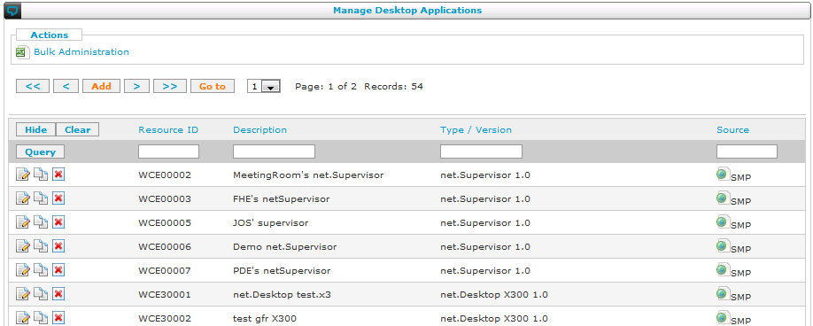
Navigate to: Resources > Desktop apps
This is where you add desktop applications to your set-up. The SMP shows you a list of all the applications defined in your system.
The details of the desktop applications are explained in the
resource reference guide.
Permissions
Navigate to: Resources > Permissions
This is where you define the permissions for your set-up. The SMP shows you a list of all the permissions defined in your system.
The details of the permissions resource are explained in the
resource reference guide.
Overview
This menu of the SMP interface has the following items:
| Menu item |
Service |
Non-clustered SOP |
Clustered SOP |
Cluster level |
Clone level: menu unavailable |
| Basic Reports |
Call statistics (basic) |
|
|
|
|
| Advanced Reports |
Call statistics (advanced), Queue statistics, |
|
|
|
|
| Time Slots |
N/A |
|
|
|
|
| Price List |
N/A |
|
|
|
|
The following sections discuss these menu items one by one.
Introduction
To get an overview of the usage of your Escaux telephony solution, the SMP offers two types of reporting: basic and advanced CDR reporting. Aside from these two, the solution also offers reporting on presence and on queue usage for call centres and receptions.
You can use basic CDR reporting to get a quick overview of certain types of calls. For example, you can select all calls to mobile numbers and get an overview of total cost of those calls per extension. Advanced CDR reporting is similar but offers more flexibility than the standard reporting. First of all, reports can be scheduled to run automatically and to be sent by e-mail. Second, Escaux UCS reporting is consolidated: reports for all sites can be generated as easily as for one site or one user. Even when the appliances are located on different sites of the company, the consolidation will still gather all the information and make up a single report. This means that your monthly or quarterly report for management can be fully automated for all the sites of your company.
An administrator can generate two forms of presence reports: State Transition Record (STR) and State Duration Record (SDR) reports. Every time a user’s status changes, the solution logs an STR. STRs therefore give an overview of who changed his status when (including automatic status changes, for example, by the Exchange calendar integration). SDRs act as an accumulator of STRs: they indicate the amount of time every user stayed in a certain status before changing to another status. An SDR report is therefore useful to get an overview of how the solution is used.
To report on the performance of your call center or your reception setup, Escaux offers advanced reporting on the usage of queues. Reports can be summarised by queue, agent, call result, time or date, caller and called numbers.
Basic reporting
Navigate to: Reporting > Basic Reports
The SOP keeps the details of all internal and external calls in an internal database. These details can be consulted online. In order to assist you with the analysis of this large amount of data the SMP allows you to define reports. The basic reporting tool allows you to define and save several reports. When requesting a large amount of data the Basic reporting could give a timeout error, this is to avoid overhead on the sop. To make such a large request work you need to use advanced reporting.
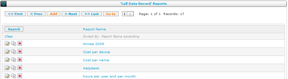
- When clicking on the report name, you can consult the report.
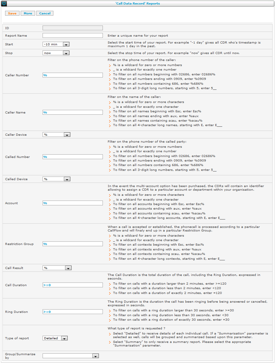
- When clicking on the 'Change' button next to a report name, you can define the report details as shown below:
When using Basic Reporting, all processing is done on the SOP and may have a degrading effect on the voice quality.
Remark: With version 4.7 or higher of SMP, for each basic report, 2 links appears in order to properly view the report as csv file:
- dot as decimal mark: The decimals are indicated by a dot.
- comma as decimal mark: The decimals are indicated by a comma.
You can choose the best link in function of the language of your spreadsheet program which imports the data.
Advanced reports
Navigate to: Reporting > Advanced Reports
Besides CDRs (Call Data Records), advanced reporting allows to report
on STRs (State Transition Records) and SDRs (State Duration Records).
These new data records store how various attributes change over time.
For instance if a user changes his status from Office to Absent, this
state change is recorded in an STR. It is often interesting to know
how long a certain state was retained, e.g. how long a user has been
in status Office. Therefore, based on the STRs, SDRs are calculated.
Each of these three types of data has a report type:
- CDR : ReportCDR : Call Data Records
- STR : ReportSTR : State Transition Records
- SDR : ReportSDR : State Duration Records
Refer to the
Resource Reference Guide for
a description on how to use these reports.
In contrast to Basic Reporting, the reports are calculated on the SMP,
offloading the processing from the SOP. For this to work, the
data must first be copied using the
SyncCDRDB Task. During this
process, the SDRs are calculated and certain data is added to the raw
CDRs, including the estimated price.
In order for a correct price estimate to be calculated, both the
Price List and the Timeslots must be correctly defined. (See below)
Another advantage of advanced reporting is that it can be used by
regular users (non-administrators) (See Permissions above).
Advanced Reporting is an optional feature. If you do not see the SyncCDRDB task, it is unavailable.
Scheduled Reports
It is possible to have reports automatically generated at regular intervals, e.g. every month.
To schedule a report:
- Go to the configuration screen of the report you want to schedule
- Set "Run automatically" to e.g. "Every 1st of the month"
- Enter your email address in the "Email report to" field (or several email addresses separated by commas)
- Press "Save". There is no need to do apply changes.
Time slots
Navigate to: Reporting > Timeslot Definition
The price of a call is often dependent of the time of day, whether it is in a weekend or not, and other conditions. A timeslot is typically something like "PEAK" or "OFFPEAK". For each such timeslot a different pricing can be used.
To determine which timeslot to use for rating a certain call, the rules are evaluated in order of their rule number. The first rule for which the time specification matches the call's date and time is used. The timeslot name of that rule will be used to lookup the price in the price list.
The time specification is expressed by 5 components seperated by whitespace: (crontab format)
- minute: 0-59
- hour: 0-23
- day of month: 1-31
- month: 1-12
- day of week: 1-7 (7=Sunday)
For more info or a cheatsheet :
https://crontab.guru/
Each component can be a comma-separated list like '1,2,3', a range like '1-3' or '*' to match anything.
Examples:
- '* * * * 6,7': weekend
- '* 18-23 * * *': evening from 6PM
- '* * 25 12 *': christmas
- '* * * * *': matches everything
Price lists
Navigate to: Reporting > Price List
The price list associates a price with each access code and timeslot combination. The rating engine will use this information in order to calculate the price for each CDR (call data record). Separate prices can be used for call set-up and for per-minute pricing.
As an example, the SMP is populated with access codes for Belgium. It is the responsibility of the administrator to adapt the prices in function of the price given by his providers.
Overview
This menu will only appear if your contract is based on the Unification Point Licensing model.
| Menu item |
Minimal Access Level |
Non-clustered SOP |
Clustered SOP |
Cluster level |
Clone level |
| View Licenses |
poweroperator |
|
|
|
|
| Manage Licenses |
smpadmin |
|
|
|
|
| Contracts |
poweroperator |
|
|
|
|
| UP Account |
admin |
|
|
|
|
| SMP UP Account |
smpadmin |
|
|
|
|
In the Unification Point Licensing model, all extensions, resources and modules must be covered by an appropriate license.
The administrator can create and modify extensions, resources and modules freely as long as everything is covered by a license. This is checked when doing an apply changes.
The reseller can add and remove licenses as long as the total 'cost' of the licenses is within the contract. The cost is expressed in Yearly Required UPs (YRU).
The reseller can create contracts, thereby consuming UPs from its UP account.
The reseller can consult the balance and transaction of his UP account.
The following sections discuss these menu items one by one.
View Licenses
Navigate to: Licenses > View Licenses
Licenses allow you to use certain types of objects in you configuration. There are three types of licenses:
- Resource licenses allow you to use resources like interfaces, net.Desktop, etc.
- Profile licenses allow you to create extensions having a profile with a certain level of complexity (basic, advanced,...)
- Module licenses allow you to install certain modules.
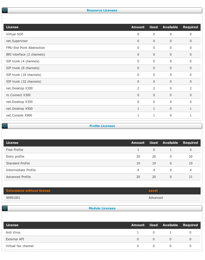
This screen shows all possible licenses that exist and for each, some counters:
- Amount: the amount of licenses you have purchased
- Used: the amount of licenses you are currently using based on your configuration (note: you cannot use more licenses than you have purchased)
- Available: the amount of licenses you have but are not used (= amount - used)
- Required: the total amount of licenses you need as a minimum based on your configuration (note: required > used if you don't have enough licenses)
Note that licenses can be valid for different kinds of objects, e.g. a license for net.Desktop X300 is also valid for net.Desktop X500. This means that the report may tell you that you require a net.Desktop X300 license while you have a X500 which is also good.
Manage Licenses
Navigate to: Licenses > Manage Licenses
If you have sufficient rights, you can use this screen to change the mix of licenses as long as you stay within the contractual YRU (yearly required unification points)
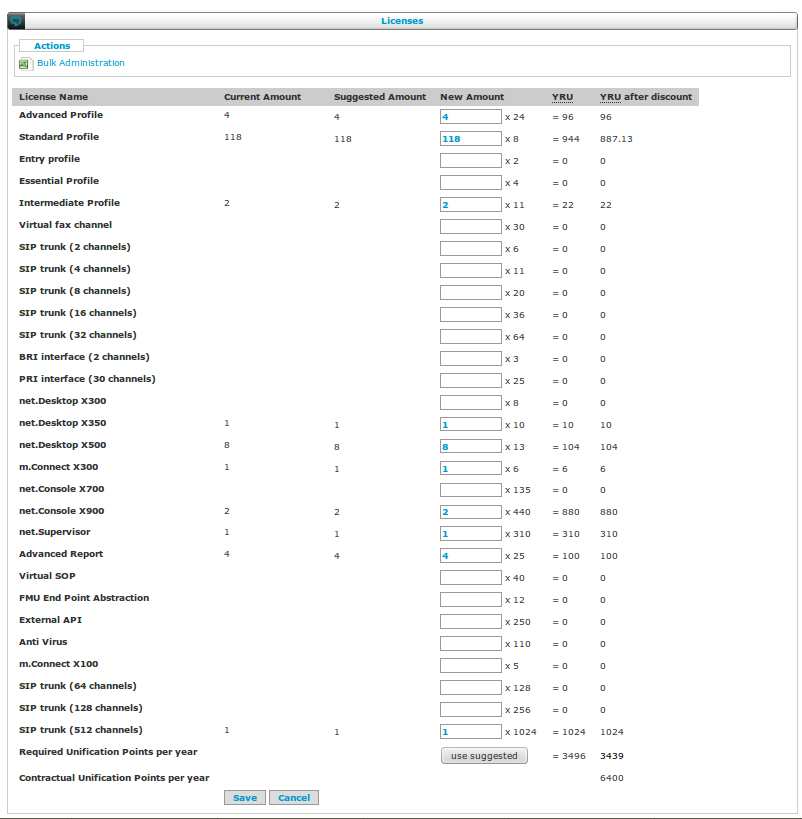
For every license, following information is shown:
- the current number of licenses you have
- the suggested number of licenses you need based on your configuration
- a textbox to change the current number of licenses
- the amount of YRU per license
- the total YRU (= number of licenses * YRU per license)
- YRU after discount (= number of licenses * YRU per license * (Threshold + (1 - Threshold) * Discount Factor^(MAX(number of licenses/Step-1;0))) )
- YRU per license, Threshold, Discount Factor and Step are determined by the pricelist.
For certain licenses a discount might be offered depending on your pricelist. The YRU after discount column will indicate the number of YRU needed to support your current configuration.
At the bottom of the screen, the total YRU for all licenses is shown and compared to the contractual YRU. The total should not exceed the contractual.
The "Use suggested" button will simply copy all suggested values to the input fields. No changes take place until you press Save.
Contracts
Navigate to: Licenses > Contracts
A contract specifies a number of UPs to be consumed every year in exchange for the right to use licenses up to that amount of YRU (yearly required unification points)
Given sufficient rights, you can create new contracts or in some cases alter existing contracts.
Initially a contract is in the
NEW state. At this state you can still alter and even delete the contract.
Once a contract is
CONFIRMED, the YRU can be used for licenses.
Two weeks after confirmation, the contract goes to
ACTIVE state. At this point, UPs will be consumed and changes can no longer be made to the contract.
When ceasing an active contract, it first goes to the
CEASING state. This means that a cease is been requested but the contract duration has not yet lapsed.
Once the contract duration is lapsed and the contract is in ceasing state, it will not be renewed and it goes to
CEASED state.
DirectedGraph Error (1): Processing .convert -density %DENSITY|N% -geometry %GEOMETRY|S% %INFILE|F% %OUTFILE|F%
01: digraph G
02: {
03: rankdir="LR"
04: graph [fontsize=16, fontname=Helvetica, labeljust="l"];
05: node [fontsize=12, fontname=Helvetica];
06: edge [fontsize=10, fontname=Helvetica];
07:
08: NEW -> CONFIRMED [label="confirm"];
09: CONFIRMED -> ACTIVE [label="2 weeks"];
10: ACTIVE -> CEASING [label="cease"];
11: CEASING -> CEASED [label="contract duration lapsed"];
12: }
13:
The list view shows all contracts for the current SOP or cluster.
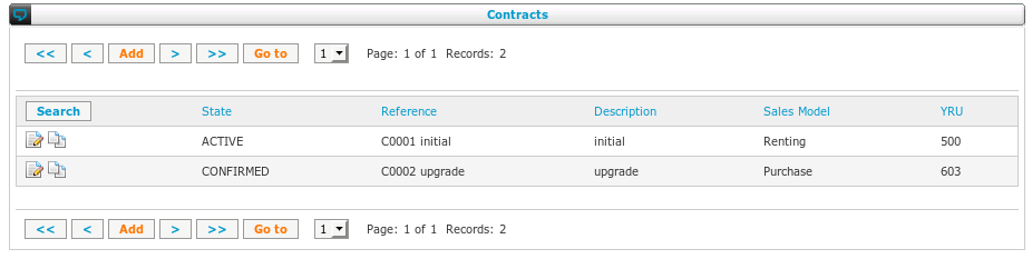
The edit screen reveals following fields:
- Reference: free text field intended to store a contract number
- Description: free text field intended to store a human readable description
- Initial Duration: the minimum contract duration
- Price List: cannot be changed
- Charging Schedule: how payments are scheduled in time
- YRU: the contract value expressed in Unification Points per year
- Suggested YRU: the minimum YRU required for the licenses specified in the Manage Licenses screen, taking into account other contracts
- State: the state of the contract (see also above):
-
NEW: all fields can be changed, YRU is not taken into account
-
CONFIRMED: all fields can be changed, YRU is taken into account
-
ACTIVE: contract is frozen, billing started, YRU is taken into account
-
CEASING: contract is frozen, YRU is taken into account, contract will ceased at next cease opportunity
-
CEASED: contract is frozen, YRU is not taken into account
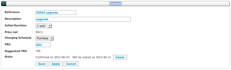
UP Account
Navigate to: Licenses > UP Account
Note that while you can consult this report from any SOP or cluster, the report is for your UP account and is not related to a particular SOP or cluster.
Your UP account is like a bank account and this report shows the transactions on that account. In the past and also a prediction for the future based on the current contracts.
Following types of transactions can occur:
- consumption: this is by far the most common transaction: UPs are consumed by a contract
- purchase: you have purchased UPs from Escaux.
- expiration: UPs you have purchased earlier remained unused for longer than contractually agreed and will (or have) expired.
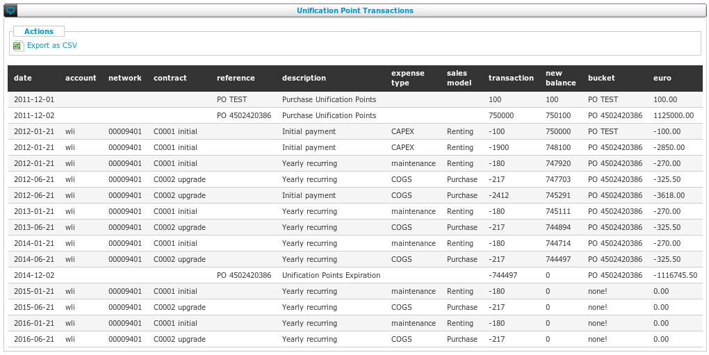
The report has following columns:
- date: can be in the past or future (=forecast)
- account: the account code of the contract consuming UPs
- network: the network name of the contract consuming UPs
- contract: the reference of the contract consuming UPs
- reference: the reference of the purchase (PO)
- description: the description of the contract consuming UPs
- expense type: as defined in the payment schedule of the contract consuming UPs
- sales model: as defined in the payment schedule of the contract consuming UPs
- transaction: the amount of UPs debited or credited from the account
- new balance: the balance of the account after this transaction
- bucket: the oldest UPs are consumed first, this is the reference of the purchase from which the UPs are consumed
- euro: the consumed UPs expressed in euros based on the purchase price
Overview
This menu of the SMP interface has the following items:
| Menu item |
Minimal Access Level |
Service |
Non-clustered SOP |
Clustered SOP |
Cluster level |
Clone level |
| Server Configuration |
poweradmin |
N/A |
|
|
|
|
| Module Configuration |
poweradmin |
N/A |
|
|
|
|
| Site Configuration |
admin |
N/A |
|
|
|
|
| Network Configuration |
admin |
N/A |
|
|
|
|
| Action Management |
admin |
N/A |
|
|
|
|
| Machine Status |
operator |
N/A |
|
|
|
|
| Subsystem Status |
poweroperator |
N/A |
|
|
|
|
| Phones Status |
operator |
N/A |
|
|
|
|
| Event History |
poweroperator |
N/A |
|
|
|
|
| Create Configuration Snapshot |
admin |
N/A |
|
|
|
|
| Restore Configuration Snapshot |
admin |
N/A |
|
|
|
|
| Lock Configuration |
admin |
N/A |
|
|
|
|
| System Tasks |
admin |
N/A |
|
|
|
|
The following sections discuss these menu items one by one.
Introduction
The menu "Advanced" is a collection of status tools and advanced configurations. This section describes each option one by one.
Server configuration
Navigate to: Advanced > Server configuration
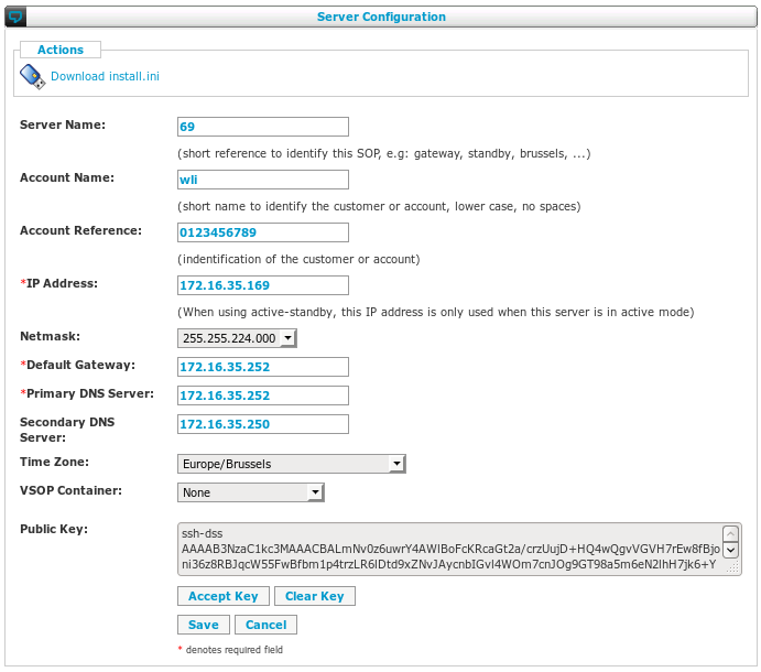
Server name
The server name can be set to anything you want to easily identify the SOP. The name has to be unique in your cluster.
Account name, account reference (smp owner only)
SMP Owners can set the account name and reference of a sop. The account name and reference are two identifiers for the customer. The account name is mandatory, the account reference is an additional optional identifier.
Network configuration
Mandatory basic IP network configuration parameters. Additional, more advanced parameters can be found in the Network module. In case of active-standby high-availability, an additional IP address is configured in the High Availability modele.
Time Zone
This is mandatory to ensure proper display of the time in various places including phones. SOPs in a cluster can be in different time zones. Phones on the same SOP cannot.
VSOP container (smp owner only)
This must be set if the SOP is not a physical machine, but rather is a virtual SOP (vSOP), i.e. a virtual machine running on a host SOP. The host SOP has a VSOP resource for every vSOP container. With this dropdown you can specify on which host SOP and in which container this SOP is running.
Public Key
The SOP maintains a secure connection to the SMP. The SMP needs to know that the SOP that is connecting to the SMP is really the one it claims to be. To do that the SMP needs to know the public key of the SOP. While the SOP installation process automatically sends the public key to the SMP, it is finally up to you, the administrator, to say that you trust the key.
If the SOP has sent its key to the SMP, you will see the key in the text box. If you trust the key, you can use the
Accept Key button to install the key on the SSH routers and allow the SOP to establish the connection with the SMP.
The key cannot be altered by hand, it can only be published from the SOP:
- during the installation of the SOP
- by using the SOP Shell
Navigate to: Configuration > Key management > Regenerate authentication keys
If a key is already on the SMP, you cannot publish a new one. You will see following message on the SOP when attempting to publish a new key:
Not authorized to register key on SMP
In that case you have to use the
Clear Key button to remove the key from the SMP.
Module configuration
Navigate to: Advanced > Module Configuration
This menu item shows the list of modules that are present on your system.
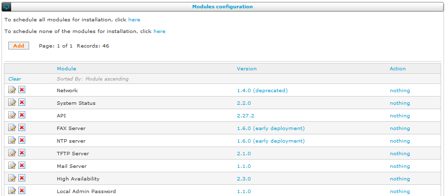
To upgrade a module, click on the version number. The module is updated automatically to the latest general deployment version. You should reinstall it to activate the changes. Reinstallation can also be necessary for other, module specific reasons. To reinstall a module that was previously installed, click on the
\ change button and select install:
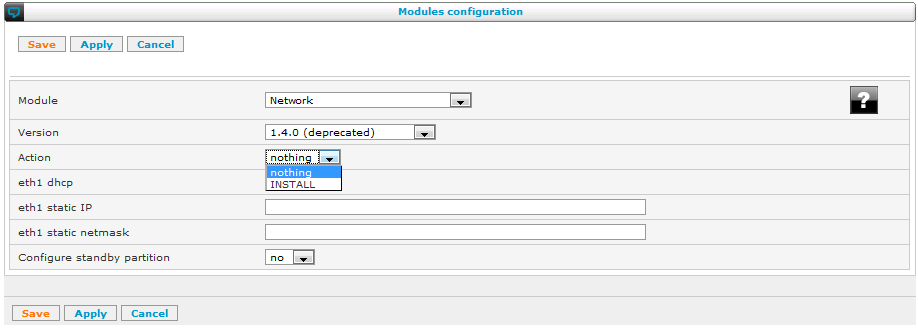
Afterwards, use the "Install Modules" button at the bottom of the module list to install the modules that have been marked to be installed.
If you have accidentally selected a module for reinstall, you can click again on the
\ change button to deselect the module for installation.
To add a new module, click "Add" in the module list. You can choose the module from a list and select if you want to install it:
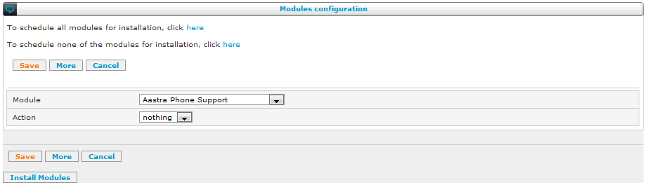
For more information about modules, please refer to the
action reference guide.
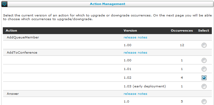
Machine status
Navigate to: Advanced > Machine Status
When you have selected a SOP to work on in the menu bar, this option will show you status information about the SOP hardware. The status overview will give you a visual indication of the most important system parameters of the SOP machine.
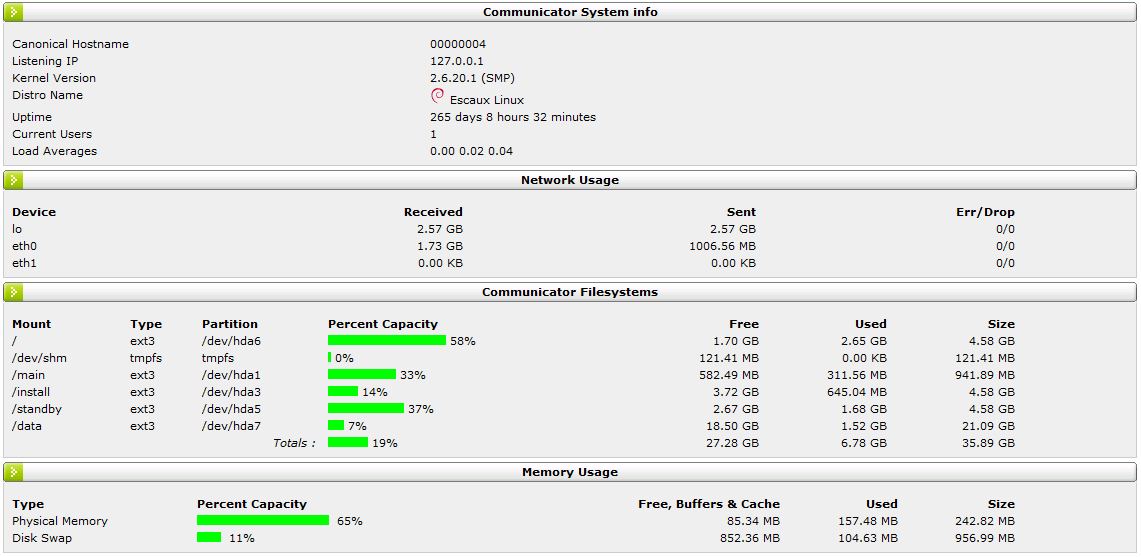
Subsystem status
Navigate to: Advanced > Subsystem Status
The subsystem status screen shows you a visual overview of the subsystems that are running on your Escaux SOP. This overview is practical when debugging problems on one of your SOPs.
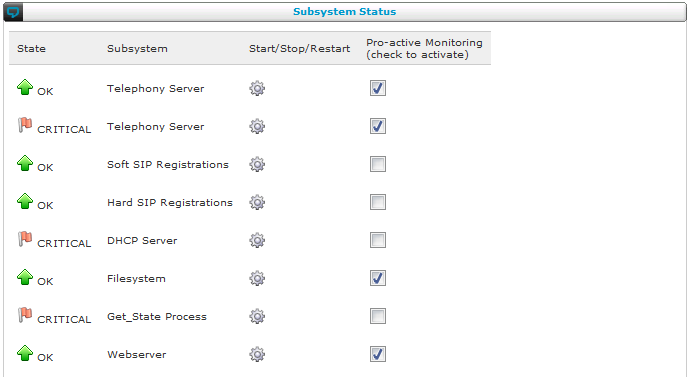
Phone status
Navigate to: Advanced > Phone Status
This menu shows a list of all the phones installed in your set-up with their status (registered or not registered). You can reboot an individual telephone from the SMP or you can reboot all of phones of the same type at once.
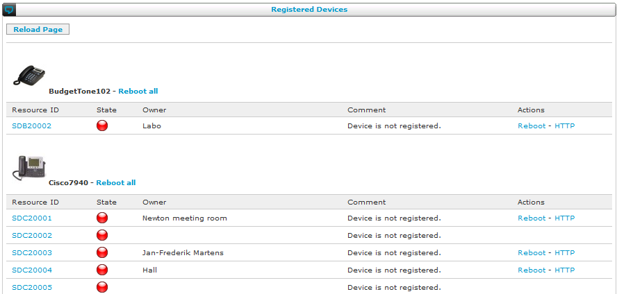
Event history
Navigate to: Advanced > Event history
The event log menu item brings up the most recent events in the event log in a browsable view. The event log is used to find problems with a SOP.
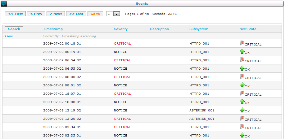
Snapshots
To make a full back-up of your configuration (except Users and some fields in the Server/Cluster Configuration page):
Navigate to: Advanced > Create Configuration Snapshot
The snapshot will start immediately.
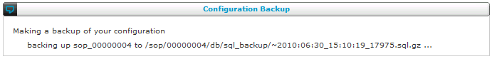
After the snapshot is finished, you get a result screen:
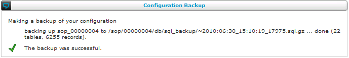
To restore a snapshot of your configuration:
Navigate to: Advanced > Restore Configuration Snapshot
You can select which snapshot you want to restore. The SMP guides you through the steps to restore the configuration to the older version.
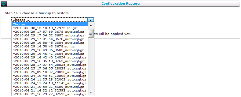
Lock configuration
Navigate to: Advanced > Lock configuration
If you need to lock the configuration, you can provide a reason why you are locking. One good reason is a bulk upload of part of the configuration: the lock will guarantee that no other administrator can make modifications while the bulk upload is in progress. This makes the bulk upload an atomic operation.
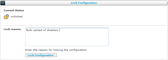
After you locked the configuration, the top bar of the SMP menu shows an indicator that the configuration is locked:
To unlock, just navigate to the same menu item you used to lock the configuration. The SMP will show you that the configuration is locked, by whom it is locked and for what reason. You can unlock the configuration using the button. If you are not the administrator who locked the configuration, then make sure you discuss the situation with the administrator who locked the configuration before unlocking.
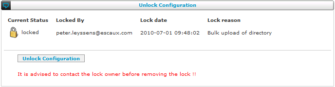
The SMP top bar will no longer display the lock indicator after unlocking the configuration.
System tasks
Navigate to: Advanced > System Tasks
From this screen you can define, modify, remove and run certain tasks. For example, SyncCDRDB is a process that needs to be run before you can use the advanced reporting.
Just like "Apply Changes", all system tasks run in the background, independently of your browser. Although not recommended, you may navigate away before it is finished.
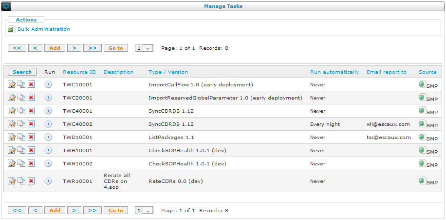
If you add a new system task, you must first choose between the types of system tasks that are available on your set-up:
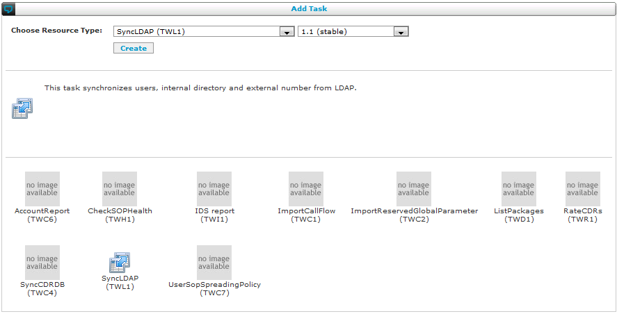
After selecting the type of task, you are presented with an additional screen to set parameters about how the task runs and reports:
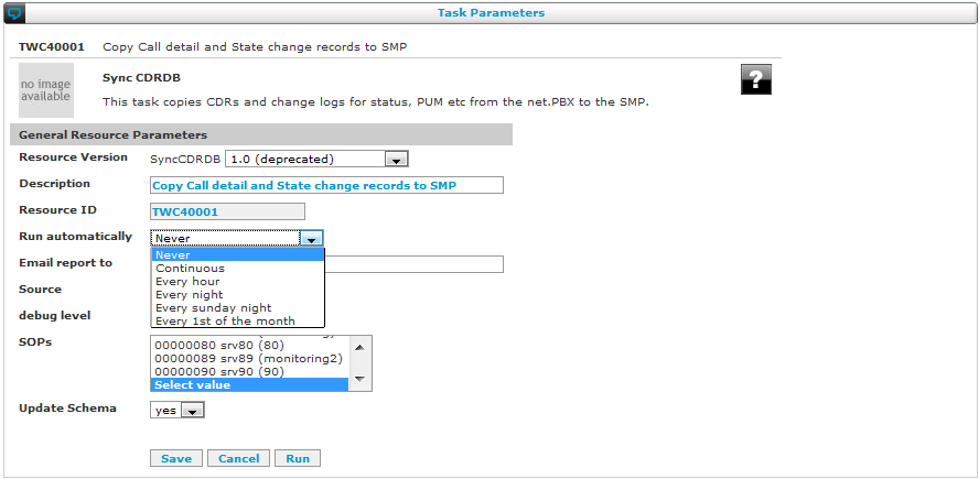
A task can be scheduled to only run when started manually ("Never" run automatically), to run every month, every week, every day, once each hour or "continuously".
The option to run a task continuously should be used with caution to prevent overloading the SMP. The task will be scheduled to run every minute. Note that only one task may run at the same time per SOP, if a task that takes a long time is scheduled too frequently it will delay other tasks of the same SOP. The "Continuous" mode has been introduced to run the PhoneZeroConf task and should not be used for any other task unless explicitly stated in the documentation of that task.
Please consult the
Resource Reference Guide for all the details on the configuration parameters of each specific task.
Use cases and scenarios
Setting a maximum call duration
Warning: Can't find topic EscauxCustomerDocs.ScenarioMaxCallDuration
Prompt recording callflow
Introduction
Default call flow templates are provided with your Escaux UCS. The following explanation details the Prompt Recording call flow, located at root extension *208.
Goals
The goal of this scenario is to provide the ability to record a prompt through a phone by composing an extension.
Requirements
These are the restrictions and prerequisites for this scenario:
- Needs the following Escaux UCS modules installed :
- Asterisk 1.2x version 2.7 or higher
- The following concepts are illustrated by this application note:
- SetLanguage action
- RecordPrompt action
Implementation
- The first action used is the SetLanguage action.
- Only default English prompts are distributed in standard.
- This action affects only the voice menu prompt and not the recording prompt. In order for example to record a French prompt, the administrator must fill the correct filename (See administration guide prompt reference for more information).
- The RecordPrompt action is used here using the 'skip introduction message' option to remove the default prompt message.
Usage and examples
Prompt Recording scenario:
- The administrator configures an extension with the Recorder.Record call flow (See example 850)
- The administrator configures the "Prompt Used For the recording" parameter of the Recorder.Record call flow (Click on corresponding 'Recorder.Record' URL) (*)
- The speaker compose the extension 850
- A voice menu propose 2 options:
- - Press 1 to record the announcement
- - Press 2 to hear the announcement
Hints
- The administrator can add a version (example: SpecialHolidayV2) to the filename specified in (*) in order to record prompt without affecting currently used prompt. This let decision maker review quality of prompt recording.
- In a second step, the administrator can update the global prompt parameter to use the new filename.
Creating an IVR
Warning: Can't find topic EscauxCustomerDocs.ScenarioIVRMenu
Pickup system
Group pickup
To pick up a call in the same group, call *8. *8 is the default key combination, but it can be changed through the
Asterisk-1.2x module.
Groups are defined in the internal directory and are limited to a maximum of 30 groups.
Users that belong to the same group can pick up each others calls. It is not possible to be in multiple groups at the same time.
To define in which group a user belongs, log in on the SMP
Navigate to: Directory > Internal directory
Pick up an extension based on specific criteria
Introduction
The pickup system enables a user to pickup a call based on different criteria. The following pickup types are available:
- OfficePickup: pickup a call from a user in the same office
- SitePickup: pickup a call from for a user in the same group
- DepartmentPickup: pickup a call from for a user in the same group
- DirectedPickup: ask the user the extension to pickup
These pickup types all work in the same way, the only difference is that they use a different field from the internal directory to do the pickup: the Office field, the Site fiel, the Department field or the extension field
Note that these different types can coexist: you are not limited to one of these types and can use them all together.
Implementation
Office Pickup
This callflow will allow you to pick up a call from a colleague who is located in the same office as you.
When userX calls the number to do an office pickup, the callflow will first lookup all parameters for userX, including userX's office. After this, it will do a 'pickup' on criteria office. The value for the office will be the office that has been found for userX
Creating the callflow
Navigate to: Communication Flow Studio > Callflows
- Click on add and define following fields:
- Root Extension : Any available number you like
- Description : Office pickup
- First Action : GetExtensionsInfo 1.1
- Click on save
- Open the callflow you just created
- Configure the parameters for GetExtensionInfo
- extensions : ${CALLERID(num)}
- press submit
- Add the next action: Pickup 2.0
- Criteria : LastUserOffice
- PickupVariableValue : ${ExtOffice}
Creating the profile
Navigate to: Communication Flow Studio > Profiles
- Click on add and define the following field:
- Profile Name : OfficePickup
- Type : Static
- Press save
Linking the callflow and the profile
Navigate to: Communication Flow Studio > Callflow assignment
- Click on add and define the following field:
- Application Selector : the latest general deployment version of startDynamicApplication
- Profile : OfficePickup
- Status : Office
- CallFlow Root : The number of the callflow you just created
- Press save
Adding an extension
Navigate to: Directory > Internal Directory
- Click on add and define the following fields:
- Extension : a number of your choice
- First name : (for example:) Office
- Last name : (for example:) Pickup
- CallFlow : OfficePickup.Office
Site Pickup
This callflow will allow you to pick up a call from a colleague who is located on the same site as you.
When userX calls the number to do an office pickup, the callflow will first lookup all parameters for userX, including userX's office. After this, it will do a 'pickup' on criteria site. The value for the site will be the site that has been found for userX
Creating the callflow
Navigate to: Communication Flow Studio > Callflows
- Click on add and define following fields:
- Root Extension : Any available number you like
- Description : Site pickup
- First Action : GetExtensionsInfo 1.1
- Click on save
- Open the callflow you just created
- Configure the parameters for GetExtensionInfo
- extensions : ${CALLERID(num)}
- press submit
- Add the next action: Pickup 2.0
- Criteria : LastUserSite
- PickupVariableValue : ${ExtSite}
Creating the profile
Navigate to: Communication Flow Studio > Profiles
- Click on add and define the following field:
- Profile Name : SitePickup
- Type : Static
- Press save
Linking the callflow and the profile
Navigate to: Communication Flow Studio > Callflow assignment
- Click on add and define the following field:
- Application Selector : the latest general deployment version of startDynamicApplication
- Profile : SitePickup
- Status : Office
- CallFlow Root : The number of the callflow you just created
- Press save
Adding an extension
Navigate to: Directory > Internal Directory
- Click on add and define the following fields:
- Extension : a number of your choice
- First name : (for example:) Site
- Last name : (for example:) Pickup
- CallFlow : SitePickup.Office
Department Pickup
This callflow will allow you to pick up a call from a colleague who is located in the department as you.
When userX calls the number to do an office pickup, the callflow will first lookup all parameters for userX, including userX's office. After this, it will do a 'pickup' on criteria department. The value for the department will be the department that has been found for userX
Creating the callflow
Navigate to: Communication Flow Studio > Callflows
- Click on add and define following fields:
- Root Extension : Any available number you like
- Description : department pickup
- First Action : GetExtensionsInfo 1.1
- Click on save
- Open the callflow you just created
- Configure the parameters for GetExtensionInfo
- extensions : ${CALLERID(num)}
- press submit
- Add the next action: Pickup 2.0
- Criteria : LastUserDepartment
- PickupVariableValue : ${ExtDepartment}
Creating the profile
Navigate to: Communication Flow Studio > Profiles
- Click on add and define the following field:
- Profile Name : DepartmentPickup
- Type : Static
- Press save
Linking the callflow and the profile
Navigate to: Communication Flow Studio > Callflow assignment
- Click on add and define the following field:
- Application Selector : the latest general deployment version of startDynamicApplication
- Profile : DepartmentPickup
- Status : Office
- CallFlow Root : The number of the callflow you just created
- Press save
Adding an extension
Navigate to: Directory > Internal Directory
- Click on add and define the following fields:
- Extension : a number of your choice
- First name : (for example:) department
- Last name : (for example:) Pickup
- CallFlow : DepartmentPickup.Office
Directed call Pickup
This callflow will allow you to pick up a call from a specific colleague after having entered the colleagues phone number.
When userX calls the number to do an office pickup, the callflow will first lookup all parameters for userX, including userX's office. After this, it will do a 'pickup' on criteria department. The value for the department will be the department that has been found for userX
Creating the callflow
Navigate to: Communication Flow Studio > Callflows
- Click on add and define following fields:
- Root Extension : Any available number you like
- Description : directed call pickup
- First Action : GetDigit 1.04
- Click on save
- Open the callflow you just created
- Configure the parameters for GetDigit
- message : A prompt that asks for the number. You can use the default prompt 'PumExtensionPrompt'
- variable : an existing extension variable that has been configured as 'uservar', for example 'StdExtension'
- digith_length : the number of digits your internal extensions have
- press submit
- Add the next action: Pickup 2.0
- Criteria : LastUserExt
- PickupVariableValue : The variabele you configured in the getDigit action
Creating the profile
Navigate to: Communication Flow Studio > Profiles
- Click on add and define the following field:
- Profile Name : DirectedPickup
- Type : Static
- Press save
Linking the callflow and the profile
Navigate to: Communication Flow Studio > Callflow assignment
- Click on add and define the following field:
- Application Selector : the latest general deployment version of startDynamicApplication
- Profile : DirectedPickup
- Status : Office
- CallFlow Root : The number of the callflow you just created
- Press save
Adding an extension
Navigate to: Directory > Internal Directory
- Click on add and define the following fields:
- Extension : a number of your choice
- First name : (for example:) Directed
- Last name : (for example:) Pickup
- CallFlow : DirectedPickup.Office
Remark: If you just want to pickup a call from, for example, the reception, but you don't want to allow users to pick up any extension, just replace the getDigit action by SetVar and set the value of variabele that is used in the pickup action to the extension of the reception
FAQ
Why don't I see anything on the screen when I can do a pickup
This is not possible in the current setup on the phone itself. netDesktop will show you a pop-up so you can pick up the call
Why can't I define more than 30 groups
This is a limitation of asterisk itself. If you have more than 30 groups, follow the guide 'Pick up an extension based on specific criteria' and use the office field instead of the group number
What if multiple phones are ringing in, for example, a office pickup
If multiple phones are ringing and you do a pickup, the system will pickup a random phone that is ringing
Directed call pickup
Introduction
Default Call Flow templates are provided with your Escaux UCS. This application notes explains the Directed Call Pickup call flow, located at root extension *200.
Goals
The goal of this scenario is providing the ability to pickup a call for a specific extension
- This Directed Call Pickup feature implementation provides the following user experience:
- A calls B
- The B phone rings but B does not answer
- C presses the 'Directed Call Pickup' button on his phone. This composes the 'Directed Call Pickup' extension
- After the beep, C composes the extension of B followed by '#'
- As a result, C talks to A
- The following concepts are illustrated by this application note:
- Escaux UCS system prompt usage in a prompt Global Parameter
- GetDigit action
- Redirect action
- Application Selector version selection.
Implementation
In the Directed Call Pickup call flow,
- The Global Parameter 'PickupPrompt' is used:
- Parameter Name: PickupPrompt
- Parameter Type: PROMPT
- Parameter Value: ../beep (prefix '../' means it is a system prompt. See PromptReferenceGuide for more information)
- The GetDigit action is used:
- To play the 'PickupPrompt' beep.
- To store in the temporary variable "PickupExtension" the '#' terminated digit string corresponding to the extension which must be picked up (Without the '#')
- In order to make this script working, it is necessary that the extension which is picked up is linked to a call flow which uses the STARTDYNAMICAPPLICATION version between 2.00 and 5.x (see ActionApplicationSelector for more information) in order to auto-generate the corresponding complete Pickup Extension code. (999999001 + extension)
- The Redirect action is used:
- To redirect the call to the corresponding Pickup Extension code.
- By prefixing the Directed Pickup prefix code 999999001 to ${PickupExtension} (Redirect Action Parameter = 999999001${PickupExtension})
Assigning a phone key to the 'Directed Call Pickup' feature.
- Assuming the internal extension '800' has been dedicated to the 'Directed Call Pickup' application.
- In order to bind a phone key to the this internal extension '800',
- Locate the Phone Id which needs to access this feature (Resources > IP Phones). (Example SDG30009)
- Click on the corresponding Phone Profile.
- A phone specific web interface appears.
- Configure a speed dial '800' according to your needs.
Status browsing callflow
Introduction
Default call flow templates are provided with your Escaux UCS. This application notes explains the Status Browsing call flow, located at root extension *203.
Goals
The goal of this scenario is to provide the ability to change the status via a phone through an IVR.
Requirements
These are the restrictions and prerequisites for this scenario:
- Needs the following Escaux UCS modules installed :
- SOP API version 2.1 or higher (not installed on the template)
- Asterisk 1.2x version 2.6 or higher
- Needs 'stable-2' or more recent SMP graphical user interface
- Needs all user call flow use application selector version 3.1 or higher (see ActionApplicationSelector)
- For each [status_name], a prompt 'status_[status_name] must be recorded or uploaded.
- The ${DefaultStatus} global parameter must contain the status in which the extension must be put when logging on this extension. (Typicaly: 'Office' status). ${DefaultStatus} is a global parameter of type ResAdminConst as documented in the Global Parameter Reference Guide
- SVE resources (SIP Virtual Escaux)
- This feature assumes that SIP Virtual Escaux (SVE) IP phones are properly configured.
- Each user of this feature has as Primary Phone a SVE resource configured with all needed informations for this user (Speed dials, Call Waiting, Directory configurations)
- For example extension 991 has SVE10001
- The following concepts are illustrated by this application note:
- SetLanguage action
- GetDigit action
- GetXPath action
Implementation
PUM Login callflow
- The first action used is the SetLanguage action.
- Only 'fr' french prompts are distributed in standard. (see PromptReferenceGuide if you need to record your own prompts in English or in another language)
- GetDigit action is used to ask the PUM user extension and the pincode.
- GetXPath (see Action55) action calls the PUM API:
- The URL calls the internal pum API method http://localhost/pum/login.pl with the following parameters:
- login ${logext}
- pincode ${logpin}
- ${CHANNEL} variable containing the SIP device phone used (ex: SDG30001)
- ${SIPCALLID} variable containing the IP address of the SIP device phone
- ${DefaultStatus} variable containing the status which must be set after the login
- The PUM login method is executed on the Escaux UCS
- The PUM login returns a XML document like this:
<pumLogin>
<channel>${CHANNEL}</channel>
<sipcallid>${SIPCALLID}</sipcallid>
<extension>${logext}</extension>
<pincode>${logpin}</pincode>
<status>${DefaultStatus}</status>
<Result>OK</Result>
</pumLogin>
- The GetXPath action stores /pumLogin[1]/Result[1] value (here 'OK') in the temporary ${Result} variable.
- The ${Result} variable is then processed in the end of the script and an appropriate voice message is played.
PUM Logout callflow
- The GetXPath action calls the pum/Logout.pl PUM API method with the foàllowing parameters:
- ${CHANNEL} variable containing the SIP device phone used (ex: SDG30001)
- ${SIPCALLID} variable containing the IP address of the SIP device phone
- The Logout PUM method is executed on the Escaux UCS
- After analysis of the XML result, the appropriate voice message is played.
Usage and examples
PUM Login scenario:
-
- A user wants to load his personal profile [ex: SVE10001] corresponding to extension [ex: 991] on a phone [SDG30001]
- The user dials the PUM Login access code on [SDG30001]. (Example 801)
- The user extension is asked. 991 is entered.
- The user pincode is asked. The user enters pincode of extension 991.
- The credential for the extension are checked.
- If the user is already logged on another phone - the user is automatically logged off from the other phone.
- The [SDG30001] reboots and [SVE10001] configuration parameters are applied on the phone.
- As a result, the name, speed dials, Caller Id, DDI, Restrictions, ... are configured now on the phone according to the [SVE10001] profile configuration.
PUM Logout scenario:
-
- The user has logged his [SVE10001] profile on the [SDG30001] phone.
- The user dials the PUM Logout access code on this phone. (Exmaple: 802)
- The phone reboot and recover his [SDG30001] configuration.
Directed call parking
Introduction
Goals
The directed call park offers the ability to transfer the called party to a park slot dedicated to a specific user. This version provides audio feedback to the user if the call has already been abandoned at the time of its retrieval.
Requirements
This version of the service supports the Escaux cluster architecture. The call to be retrieved can be parked on one or two SOPs.
Implementation
Preparation, step 1: Directed Call Parking call flow
Make sure callflow template *212 is available on your system. If it is not available you can either ask Escaux support to add it. You can also create this callflow yourself as follows:
Navigate to: Callflows > Define callflow
- Click Add
- Enter the following parameters:
- Root Extension: *212
- Description: Directed Call Parking
- First Action: DirectedCallPark.x.xx
- Click Save
- Click on the newly created 'Root Extension' (*212)
- Modify the 'extension' parameter of the Directed Call Park Actions:
- Extension: ${ExtensionToPark:3}
- The ExtensionToPark variable will be created when we will define an access code for this outgoing call flow.
Preparation, step 2: Adapting the routing plan in order to create the feature access code
Create the _*99. routing entry to the Directed Call Parking callflow (*212 in this example)
- Go to Call Routing > Define Routes
- Click Add
- Enter the following parameters
- Telephony Route: _*99.
- Route Group: any route group which is supposed to access the Directed Call Parking Service.
- Action: MapNumber version >= 1.10
- Configure the MapNumber Action
- Number of front digits to strip: All
- Prefix applied to the number: *212 (This redirects the call to the Directed Call Parking call flow)
- Variable: ExtensionToPark ('ExtensionToPark' will contain the number as dialed by the user when Parking the call (ie *99+ extension).
Directed park retrieve, step 1: Creating the global parameters
Navigate to: SMP > Callflow Studio > Global Parameters > Prompt
Press 'Add' and fill out the following parameters:
- Parameter name: DirectedParkUnavailable
- Friendly name: Directed park user unavailable
- Owner Type: AdminConst
- Value: UserUnavailable
- Descr: Audio prompt indicating that no one is available at requested parkslot.
Press 'Save'.
Press 'Add' and fill out the following parameters:
- Parameter name: DirectedParkSop1
- Friendly name: Directed park SOP1
- Owner Type: UserVar
- Descr: First SOP where the parksot are to be retrieved
Press 'Save'.
Press 'Add' and fill out the following parameters:
- Parameter name: DirectedParkSop2
- Friendly name: Directed park SOP2
- Owner Type: UserVar
- Descr: Second SOP where the parkslot are to be retrieved
Press 'Save'.
Directed park retrieve, step 2: Importing DirectedParkRetrieve callflow
The predefined callflow is *237.
If this callflow is not present on your system, please contact the Escaux Support team.
Directed park retrieve, step 3: Creating DirectedParkRetrieve profile
Navigate to: SMP > Callflow Studio > Define Profile
Press 'Add' and fill out the following parameters:
- Profile name: DirectedParkRetrieve
- Type: Static
- Parameter1: DirectedParkSop1
- Parameter2: DirectedParkSop2
Directed park retrieve, step 4: Assigning the callflow
Navigate to: SMP > Callflow Studio > Define Profile
Press 'Add' and fill out the following parameters:
- Application Selector: STARTAPPLICATION
- Profile: DirectedParkRetrieve
- Status: Default
- Descr: Retrieve directed parked call
- Callflow: *237
Directed park retrieve, step 5: Creating the service extension
Navigate to: SMP > Directory > Internal Directory
Press 'Add' and fill out the following parameters:
- SOP: all
- SOP2: none
- Extension: 10000
- Callflow: DirectedParkRetrieve.Default
- Visibility: hidden
Directed park retrieve, step 6: Configuring service profile
Navigate to: SMP > Directory > Internal Directory
Edit callflow properties for extension 10000
- DirectedParkSop1: the first SOP where to try park call retrieval
- DirectedParkSop2: the second SOP where to try park call retrieval
Note: If this two parameters are empty the retrieval attempt will be done on the local SOP.
Directed park retrieve, step 7: adding a route for prefix *55
Navigate to: CAll Routing > Define Routes
Press 'Add' and fill out the following parameters:
- Telephony Route: _*55. (this will capture all extensions starting with *55)
- Route Group: national
- Action: MapNumber.1.11
- Action Parameter 1: leave empty
Press 'Save'
Directed park retrieve, step 8: sending the call to the DirectedParkRetrieve service
Navigate to: CAll Routing > Define Routes
Press on the Action Name 'MapNumber.1.11' of route _*55 and fill out the following parameters:
- Description: Send call to DirectedParkRetrieve service
- Number of front digits to strip: All
- Prefix applied to number: 10000
- Variable: NumberToDial
Usage and examples
The users follow this scenario:
- A calls B, B answers the call.
- B executes a blind transfer to a specific extension which contains the extension C (example: *99 + C extension)
- Phone B goes on hook and A hears music on hold. A is parked in a park slot dedicated to C.
- B calls C (by any means) and tells C he can pickup the parked call.
- C composes (on any phone) *55 + C extension and is connected to A.
DTMF based call transfer
Introduction
Goals
Call transfer is a feature that is available to all users of IP phones. This description shows how you can also offer call transfer to users with other phones. For example, if you have a number of analogue phones that are connected to an FXS, the users of these phones will also be able to transfer calls when you set up your solution according to this description. Also, DTMF based call transfers help in integrating a mobile phone into your solution: with call transfers, the feature set available to users of a mobile phone will be enlarged and their mobile phone will more capable of replacing their desk phone.
Requirements
- Asterisk-1.2 module v2.22+
- CallDevice action v1.23+
- Goto.Interface v1.32+
- Reserved Global Parameter AsteriskDialOption
Implementation
Step 1: Enable the feature for all the calls to an internal extension
Navigate to: Callflow Studio> Global Parameters > Reserved
Add the options 't' and 'T' to the global parameter AsteriskDialOption. For example, set AsteriskDialOption to 'otT'.
Step 2: Enable the feature for all the external calls going through a specific interface
Navigate to: Call Routing> Define Routes
Enable the 'DTMF call control' option of the Goto.Interface action for each trunk
Navigate to: Callflow Studio> Global Parameter > Context
- Parameter name: TRANSFER_CONTEXT
- Friendly name: call transfer restriction group
- value: NoRestrict
- Owner type: Admin var
- Description: context used for DTMF based call transfer
Usage and examples
In order to transfer a call, you first type * on your phone's keypad. The solution will answer with a voice prompt that says "Transfer". Then, you get a dial tone and you can form the number to transfer to. In the meantime, your conversation partner is put on hold and he can listen to music. After forming a phone number, you can have a conversation with the person you want to transfer to. In case he accepts, you hang up. In case he does not accept, he can accept and you can take back the call with *0.
Mobility login and logout callflow
Warning: Can't find topic EscauxCustomerDocs.ScenarioPersonalUserMobility
Caller ID manipulation for outgoing calls
Introduction
Application goals
Migrating your telephony to a solution based on the SIP technology expands the feature set that you can use: video, softphones and call recording are some of the features that you can expect to use easily. However, a few legacy features are not supported by the SIP standard yet. For example, in a legacy TDM based PBX, when A calls B, B performs an attended transfer to C, C is capable to see the caller id of A. Transferring the caller ID together with the call is not supported in SIP because it is always the person initiating the call that sends the caller id. There is no standard procedure to transform a caller id within a call.
A workaround for this is to create an outgoing callflow that maintains the caller name but replaces the caller id with the caller id of A. Escaux recommends however to use the default SIP behaviour, implementing this feature only in case there is a strong business requirement.
The outgoing call flow described here can either be triggered for all outgoing calls if the phone which makes the transfer is placed in a specific Restriction Group either via a specific access code.
Requirements
You should be familiar with callflows and how to import and export them. This is described in the section on
the callflow studio in this manual.
Application implementation
Creating the callflow
- Create a callflow *148: Call flow Studio > Define call flow:
- Root: *148
- Description: 'Overload the caller id during 2 call'
- First Action: 'SetVar 1.00'
- Save the call flow
- Click on the '*148'
- Import the following callflow:
EXTENSION;DESCRIPTION;ACTION;VAR1;VAR2;VAR3;VAR4;VAR5;VAR6;VAR7;VAR8;VAR9;VAR10;VAR11;VAR12;VAR13;VAR14;VAR15;VAR16;VAR17;VAR18;VAR19;VAR20;VAR21;VAR22;VAR23;VAR24;VAR25;VAR26;VAR27;VAR28;VAR29;VAR30;VAR31;VAR32;VAR33;VAR34;VAR35;VAR36;VAR37;VAR38;VAR39;VAR40;VAR41;VAR42;END
"_*148";"Overload the caller id during 2 call";"SetVar 1.00";"PIPE";"-";"";"";"";"";"";"";"";"";"";"*14812";"";"";"";"";"";"";"";"";"";"";"";"";"";"";"";"";"";"";"";"";"";"";"";"";"";"";"";"";"";"";"-"
"_*14812";"Present the caller when a transfer is made";"GetXpath 1.00";"http://localhost/xml/dbGetPhoneState.php?phone_id=${CHANNEL:4:8}&phone_state=%Conversation%";"Result";"/PhoneState[1]/Phone[1]/callerid[1]";"";"";"";"";"*1481208";"";"";"";"";"";"";"";"";"";"";"";"";"";"";"";"";"";"";"";"";"";"";"";"";"";"";"";"";"";"";"";"";"";"";"-"
"_*1481208";"";"SetVar 1.00";"Result";"${EVAL(${Result})}";"";"";"";"";"";"";"";"";"";"*148120812";"";"";"";"";"";"";"";"";"";"";"";"";"";"";"";"";"";"";"";"";"";"";"";"";"";"";"";"";"";"";"-"
"_*148120812";"Test if there is a result";"If 1.2";"Result";"=";"${CALLERIDNUM}";"Result";"=";"Array";"or";"";"";"";"*14812081211";"*14812081212";"";"";"";"";"";"";"";"";"";"";"";"";"";"";"";"";"";"";"";"";"";"";"";"";"";"";"";"";"";"";"-"
"_*14812081211";"No result just redirect";"Redirect 1.00";"${NumberToDial}";"";"";"";"";"";"";"";"";"";"";"";"";"";"";"";"";"";"";"";"";"";"";"";"";"";"";"";"";"";"";"";"";"";"";"";"";"";"";"";"";"";"-"
"_*14812081212";"";"ForEach 0.0";"Result";"";"TempExt";"dash";"";"";"";"";"";"";"*1481208121211";"";"";"";"";"";"";"";"";"";"";"";"";"";"";"";"";"";"";"";"";"";"";"";"";"";"";"";"";"";"";"";"-"
"_*1481208121211";"";"If 1.2";"TempExt";"=";"${CALLERIDNUM}";"";"=";"";"";"";"";"";"*148120812121111";"*148120812121112";"";"";"";"";"";"";"";"";"";"";"";"";"";"";"";"";"";"";"";"";"";"";"";"";"";"";"";"";"";"";"-"
"_*148120812121111";"Loop";"Redirect 1.00";"*14812081212";"";"";"";"";"";"";"";"";"";"";"";"";"";"";"";"";"";"";"";"";"";"";"";"";"";"";"";"";"";"";"";"";"";"";"";"";"";"";"";"";"";"-"
"_*148120812121112";"Set the caller id";"SetCallerID 1.02";"via ${CALLERID(name)}";"*14812081212111202";"${TempExt}";"allowed_passed_screen";"";"";"";"";"";"";"";"";"";"";"";"";"";"";"";"";"";"";"";"";"";"";"";"";"";"";"";"";"";"";"";"";"";"";"";"";"";"";"-"
"_*14812081212111202";"Redirect with the reight caller id";"Redirect 1.00";"${NumberToDial}";"";"";"";"";"";"";"";"";"";"";"";"";"";"";"";"";"";"";"";"";"";"";"";"";"";"";"";"";"";"";"";"";"";"";"";"";"";"";"";"";"";"-"
- Create a callflow *156: Call flow Studio > Define call flow:
- Root: *156
- Description: 'Remove the access code'
- First Action: 'SetVar 1.00'
- Save the call flow
- Click on the '*156'
- Import the following call flow:
EXTENSION;DESCRIPTION;ACTION;VAR1;VAR2;VAR3;VAR4;VAR5;VAR6;VAR7;VAR8;VAR9;VAR10;VAR11;VAR12;VAR13;VAR14;VAR15;VAR16;VAR17;VAR18;VAR19;VAR20;VAR21;VAR22;VAR23;VAR24;VAR25;VAR26;VAR27;VAR28;VAR29;VAR30;VAR31;VAR32;VAR33;VAR34;VAR35;VAR36;VAR37;VAR38;VAR39;VAR40;VAR41;VAR42;END
"_*156";"Remove access code";"SetVar 1.00";"NumberToDial";"${NumberToDial:2}";"";"";"";"";"";"";"";"";"";"*15612";"";"";"";"";"";"";"";"";"";"";"";"";"";"";"";"";"";"";"";"";"";"";"";"";"";"";"";"";"";"";"-"
"_*15612";"";"Redirect 1.00";"*148";"";"";"";"";"";"";"";"";"";"";"";"";"";"";"";"";"";"";"";"";"";"";"";"";"";"";"";"";"";"";"";"";"";"";"";"";"";"";"";"";"";"-"
Define a new route group
- Call Routing > Define Route Groups
- Add
- Name: 'Special'
- Type: 'RouteGroup'
Define a new route in this route group
- Call Routing > Define routes
- Add
- Route : _X.
- Route Group : 'Special'
- Action : MapNumber (latest version)
- Configure the MapNumber action
- Click on the newly created MapNumber
- Number of front digit to strip: All
- Prefix applied: *148
- Variable: NumberToDial
Define an access code
- Call Routing > Define routes
- Add
- Route : _*9X.
- Route Group : 'national'
- Action : MapNumber (latest version)
- Configure the MapNumber action
- Click on the newly created MapNumber
- Number of front digit to strip: All
- Prefix applied: *156
- Variable: NumberToDial
Extended huntgroups
Introduction
Goals
This application note describes how to create an 'extended hunt group' based upon call queues. The idea is to allow office workers to log in and log out from a hunt group by entering a code on their phone.
Let's assume that we have:
- two hunt groups
- 7 office workers (user1 - user7) with a Polycom IP330 phone (SDP40001-SDP40007)
- users 1 to 5 are part of hunt group 1
- users 4 to 7 are part of hunt group 2
We want to accomplish the following:
- when users 1, 2 and 3 enter code *54 on their phone, they will become part of hunt group 1
- when users 4 and 5 enter code *54 on their phone, they will become part of hunt group 1 and hunt group 2
- when users 6 and 7 enter code *54 on their phone, they will become part of hunt group 2
- if all users enter *53 on their phone, they will be removed from all ther hunt groups
Requirements
For this scenario, you need:
Implementation
Creating the queues
For each hunt group we create a queue. At the SMP create two queues:
- HuntGroup1
- Define phones SDP40001 to SDP40005 as permanent members in queue HuntGroup1
- HuntGroup2
- Define phones SDP40004 to SDP40007 as permanent members in queue HuntGroup2

Please note that all hunt group members must have their SIP phones connected to the SOP which is running the hunt group queues.
Creating a global variable
- Parameter Name: PauseAllResult
- Value: leave empty
- Type: STRING
- Owner Type: AdminVar
Creating the callflows
Login callflow
The idea of this callflow is to call an API function by using the GetXPath action. This API function will 'UNPAUSE' the member in all queues defined on the SOP. By 'unpausing' the user's phone, the user will be receiving phone calls when a call enters his particular hunt group (i.e. queue).
The API function called is:
http://a.b.c.d/xml/ccQueuePauseAll.php?phone=${primary_device_${CALLERID(num)}}&paused=false
... where a.b.c.d is the IP address of the SOP running the hunt group queues.
The return codes of this function are:
code
where code is one of the following values:
- 0: pause failed
- 1: pause succeeded
- 2: unpause failed
- 3: unpause succeeded
This callflow is depicted below. The audio prompts in this callflow are missing and must be created by the customer.
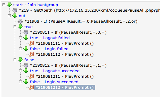
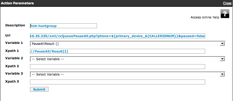
Logout callflow
The idea of this callflow is to call an API function by using the GetXPath action. This API function will 'PAUSE' the member in all queues defined on the SOP. By 'pausing' the user's phone, the user will no longer be receiving phone calls when a call enters his particular hunt group (i.e. queue).
In this case, the API function called is:`
http://a.b.c.d/xml/ccQueuePauseAll.php?phone=${primary_device_${CALLERIDNUM}}&paused=true
This callflow is depicted below. The audio prompts in this callflow are missing and must be created by the customer.
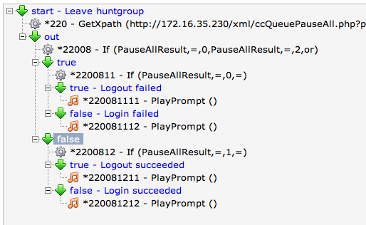
Creating Login and Logout feature codes
We will now create the login (*54) and logout (*53) codes by mapping each code to the corresponding callflow.
In our case, this means we will be mapping:
Adapt the routing plan to create the feature access code
- Create the _*54. routing entry to the hunt group login callflow (*219 in this example)
- Go to Call Routing > Define Routes
- Click Add
- Enter the following parameters
- Telephony Route: _*54.
- Route Group: any route group which is supposed to access the hunt group
- Action: MapNumber version >= 1.10
- Configure the MapNumber Action
- Number of front digits to strip: All
- Prefix applied to the number: *219
- Create the _*53. routing entry to the hunt group login callflow (*220 in this example)
- Go to Call Routing > Define Routes
- Click Add
- Enter the following parameters
- Telephony Route: _*53.
- Route Group: any route group which is supposed to access the hunt group
- Action: MapNumber version >= 1.10
- Configure the MapNumber Action
- Number of front digits to strip: All
- Prefix applied to the number: *220
Bulk administration
Introduction
Goals
Bulk Administration can be done in any screen in the directory and the resources. However, in set-ups with more than one administrator, a straight execution of a bulk administration task may lead to problems, as another administrator can modify the configuration while the bulk administration is ongoing. To avoid this, it is a good practice to lock the configuration for the duration of the bulk task and to unlock it afterwards. This section describes this parts necessary for this scenario.
Requirements
There are no specific requirements for this scenario.
Limitations
- For the Users Bulk Administration, only the users with User level will be exported. Also, you can only import users with User level.
Implementation
Preparation
Before performing any bulk administration task, the configuration must be locked. A lock on the configuration guarantees that nobody else can make modifications while your bulk administration task is being processed. To lock the configuration, use the SMP menu to lock the configuration. See menu "Advanced" section.
A maximum of 5000 lines in the imported file is allowed.
Bulk import and export
Whether you want to upload a list of users, extensions, phones or something else, the procedure starts simple: go to the menu item that you would use to manually add or configure those items. Above the list view, you will also see a bulk administration button, if that option is available for what you want to configure. The example below shows the bulk administration option in the user management section of the SMP directory menu:
When clicking the bulk administration link, you get an explanation of the procedure that includes a description of the fields of the data you will be importing:
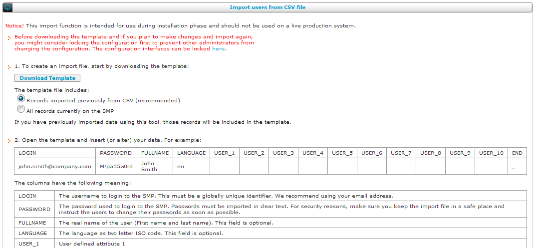
The procedure has three steps:
- You can download a template file in CSV format (comma separated values). This template can contain either all the current data of that type in the SMP, or it can contain only the previously uploaded CSV values.
- If you open this file, it will usually open in a spreadsheet program like Microsoft Excel or OpenOffice.org Calc. You can modify all the data you want, import other files and perform all other operations that your software allows. Finally, save the file again in CSV format.
- Upload the edited CSV file with the upload field.
It is possible to skip steps 1 and 2 and to upload a CSV file immediately. This can be practical if you have just exported certain data from another system, for example, user data from a CRM. However, it still makes sense to first download the template to make sure that your CSV file is formatted correctly.
In the CSV file, you have the option to include a source column or not. This gives you the following choice:
- No source column: the SMP will automatically fill in CSV as the source for the imported items. The SMP will first remove all the existing records with CSV as its source, then it will add the imported items.
- Source column: you have decided to use this column for your own purposes. You can fill in the data you like in the source column before uploading the CSV file. The SMP will first empty the complete database and then import all the items from the CSV file.
After you have uploaded the CSV file, the SMP performs a validation of the data in your file. If everything was correct, you will get a screen that shows your data:
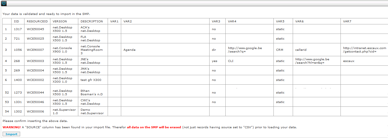
In the example above, the source column has been used for other purposes, so the SMP warns that this will overwrite the complete database.
If you have reviewed all your CSV data and you are ready to import the file, click the import button to proceed.
Advanced configuration topics
Bulk administration
Introduction
Goals
Bulk Administration can be done in any screen in the directory and the resources. However, in set-ups with more than one administrator, a straight execution of a bulk administration task may lead to problems, as another administrator can modify the configuration while the bulk administration is ongoing. To avoid this, it is a good practice to lock the configuration for the duration of the bulk task and to unlock it afterwards. This section describes this parts necessary for this scenario.
Requirements
There are no specific requirements for this scenario.
Limitations
- For the Users Bulk Administration, only the users with User level will be exported. Also, you can only import users with User level.
Implementation
Preparation
Before performing any bulk administration task, the configuration must be locked. A lock on the configuration guarantees that nobody else can make modifications while your bulk administration task is being processed. To lock the configuration, use the SMP menu to lock the configuration. See menu "Advanced" section.
A maximum of 5000 lines in the imported file is allowed.
Bulk import and export
Whether you want to upload a list of users, extensions, phones or something else, the procedure starts simple: go to the menu item that you would use to manually add or configure those items. Above the list view, you will also see a bulk administration button, if that option is available for what you want to configure. The example below shows the bulk administration option in the user management section of the SMP directory menu:
When clicking the bulk administration link, you get an explanation of the procedure that includes a description of the fields of the data you will be importing:
The procedure has three steps:
- You can download a template file in CSV format (comma separated values). This template can contain either all the current data of that type in the SMP, or it can contain only the previously uploaded CSV values.
- If you open this file, it will usually open in a spreadsheet program like Microsoft Excel or OpenOffice.org Calc. You can modify all the data you want, import other files and perform all other operations that your software allows. Finally, save the file again in CSV format.
- Upload the edited CSV file with the upload field.
It is possible to skip steps 1 and 2 and to upload a CSV file immediately. This can be practical if you have just exported certain data from another system, for example, user data from a CRM. However, it still makes sense to first download the template to make sure that your CSV file is formatted correctly.
In the CSV file, you have the option to include a source column or not. This gives you the following choice:
- No source column: the SMP will automatically fill in CSV as the source for the imported items. The SMP will first remove all the existing records with CSV as its source, then it will add the imported items.
- Source column: you have decided to use this column for your own purposes. You can fill in the data you like in the source column before uploading the CSV file. The SMP will first empty the complete database and then import all the items from the CSV file.
After you have uploaded the CSV file, the SMP performs a validation of the data in your file. If everything was correct, you will get a screen that shows your data:
In the example above, the source column has been used for other purposes, so the SMP warns that this will overwrite the complete database.
If you have reviewed all your CSV data and you are ready to import the file, click the import button to proceed.
LDAP integration
Introduction
LDAP Integration allows you to synchronize parts of you SMP's data with the data on an Active Directory server. Usage of other LDAP servers is not currently supported.
The following data can be synchronized from Active Directory:
- Internal Directory
- Users
- External Number Mapping
Project Planning : if your project planning is short, you might choose NOT to use LDAP integration because with this integration you need an Escaux SOP to be installed in your LAN prior to be able to start LDAP integration tests, which means configuration of web interfaces might be finished too late. As a workaround, you can start by using Bulk Administration, and synchronize with LDAP in a second phase.
Configuration
To use the LDAP integration feature, you must first have the "LDAP Synchronization" module installed. The module requires several parameters to be configured which can be found in the
Module reference guide
Usage
To initiate the synchronization of Internal Directory, Users and External Number Mapping from Active Directory, do the following:
- Go to the overview of the tasks and run the LDAP synchronisation task.
- Wait for the synchronization to finish. The time it takes depends on how many entries are in your directory and how many are selected by your filter. But typically this should be less than a minute or so.
- The data is now on the SMP and you should see the updated records in the web interface.
- Do Apply Changes to push the changes to the SOP
You may notice that the user's passwords are not synchronized. This is normal, whenever a user authenticates himself (when logging on the SMP or net.Desktop for example), and his user record's "source" is set to LDAP, the authentication will be forwarded to the LDAP server. Note that this offers the possibility to deactivate accounts and reset passwords instantaniously in your LDAP server without doing an LDAP sync and apply changes. However, it is not possible for the user to change his password from the SMP
.
Note that in the internal directory, Active Directory is considered
authoritive for following fields only:
- Extension
- Login
- First name
- Last name
- E-mail
- Mobile number
This means that if any of these fields change in Active Directory, a synchronization will update the field on the SMP. If you changed any of these fields manually, your change will be overwritten. However, changes made manually to other fields will be kept.
If you want to avoid the synchronization to overwrite your modifications, you can set the record's source to "SMP". That way the LDAP synchronization process will no longer touch that record. However, in that case you will also need to set the password manually because the authentication will not be going to LDAP anymore.
The default user callflow, defined in the LDAP synchronization module, is added only during creation of the user by LDAP synchronization task.
Diagnostics
When the LDAP module is installed, a new
LDAP menu will appear in the SOP Shell under
Diagnostics.
The
Test Raw function will try to fetch the raw data from the LDAP server and dump it on the screen.
The
Test Translated function will try to fetch the data from the LDAP server and apply the translations as configured in the module. The data as it would be imported in the SMP is dumped on the screen.
Redundancy
Introduction
This chapter describes the feature that is called "high availability" in technical terms (as there is a module with this name) and "active-standby set-up" in our marketing documentation. The active-standby mode is a set-up with two SOPs. One is active and processes the services requested by the users. The other one is ready to start working, but doesn't participate in the processing. It is a complete clone of the active SOP and can be activated using a short manual procedure in case of problems with the active one.
Note the difference with active-active set-ups: in this case, it's also possible to have two SOPs where one processes the services and the other one doesn't immediately participate. The difference is that in an active-active set-up, the two SOPs are independent and not clones: each SOP has its own IP address and configuration. In case one SOP goes down, the other one can take over automatically. The set-up described in this section requires a short manual intervention.
The Escaux standby SOP server is an exact copy of the active server. The configuration of the active server is synced automatically to the standby at the SMP level. In the event of a failure of the active, a switch-over procedure can be executed to let the standby take the role of the active, either temporary or permanently.
Active and standby SOPs
Active and Standby IP addresses
In order to have a redundant solution, you need 2 SOP servers (SOP_1 and SOP_2) and 3 IP addresses (IP_active, IP_standby1, IP_standby2).
- IP_active is the IP address of the active SOP, this can be either SOP_1 or SOP_2
- IP_standby1 is the standby IP address of SOP_1
- IP_standby2 is the standby IP address of SOP_2
When SOP_1 is 'active' and SOP_2 is 'standby', the IP address assigned to the ethernet interface of SOP_1 is IP_active and the IP address assigned to the ethernet interface of SOP_2 is IP_standby2.
When SOP_2 is 'active' and SOP_1 is 'standby', the IP address assigned to the ethernet interface of SOP_2 is IP_active and the IP address assigned to the ethernet interface of SOP_1 is IP_standby1.
The active SOP is also be reachable by it's standby IP address. So, to reach the SOP_1 you can simply always use IP_standby1 and to reach SOP_2 always use IP_standby2.
High Availability version 2.x
Configuration
Follow these steps to configure two SOPs as an active-standby High Availability pair.
One SOP is declared as
clone of the other SOP (the
master). This declaration must be done by ESCAUX. It replaces the "server type" setting in SMP v1.3 and below.
On the master, add or upgrade to the High Availability module 2.0 or higher. Configure the module as follows:
- SOPKEY 1 (default active): enter the SOPKEY (8 digits) of the master.
- Standby IP 1: enter the standby IP of the master.
- SOPKEY 2: enter the SOPKEY (8 digits) of the clone.
- Standby IP 2: enter the standby IP of the clone.
On the master, (re)install the following modules:
- High Availability
- Network
- SSH Peer Connectivity
Switch-over procedure
Suppose SOP_1 is currently active and SOP_2 is standby.
The following steps will switch SOP_1 to standby and make
SOP_2 active.

Voicemails, Voicemail prompts and Reporting Data aren't synchronized by default. Please ask to Escaux to synchronize them if needed.
- Switch SOP_1 to standby
- if SOP_1 is still running and you can access the Shell
- login to the SOP on the console or via ssh using it's standby IP
- The standby IP can be found on the SMP in the High Availability module configuration screen.
- in the Shell, select "System" > "High Availability" to switch to standby
- if SOP_1 is completly down
- disconnect the ethernet cable
- leave it disconnected until you succeeded to switch SOP_1 to standby mode
- Switch SOP_2 to active
- Try to ping the active IP to be sure that it's free before switching SOP_2 to active mode.
- login to the SOP on the console or via ssh using it's standby IP
- in the Shell, select "System" > "High Availability" to switch to active
- This will configure the active ip address, but the standby will also remain. If you access the Shell through ssh, you session should not be cut.
- It will also start a number of processes as required (asterisk, dhcpd, ...)
- Unplug the ISDN cables and analog devices from SOP_1 and plug them into SOP_2.
- It is advisable to reboot (using the SOP-shell) both servers in order to clear all arp cache tables and other potential residual cache.
- Do not forget to adapt subsystems status in SMP
Hints & Caveats
- Normally, all configuration changes are performed on both SOPs so that they are always kept up to date. Should however the standby become disconnected for some time during which apply changes and/or install modules is performed, this must be repeated once the standby becomes connected again. If you forget to do this you will need to do it during the switch-over procedure which is not advisable.
- The status (active or standby) is stored locally on the SOP. This is the actual operational status. It can be changed directly using the Shell. This status is kept when rebooting the SOP.
- If you switch a SOP to active, a test is done to see if the active IP address is not in use (e.g. by the other SOP). If it appears to be in use, the switch will not be performed. Make sure that the other SOP is in standby more or is disconnected from the network.
- To access the Shell, always use the standby IP address. Besides avoiding confusion, it also makes sure your session is not cut when switching from active to standby mode.
Consolidated management
Introduction
Consolidated Management allows to configure a
single logical Unified Communication system (SOP cluster) which is physically implemented by a number of
autonomous SOPs. Please note that the Consolidated Management function is only available in the 'ESCAUX Corporate Edition'.
A single logical system implies that:
- All extensions and phones are uniquely defined in a single directory interface but can be spread on different machines (SOPs)
- Intelligence is shared by all the different SOPs and is uniquely defined.
An autonomous SOP means:
- If connections between SOPs are broken, each SOP contains all the necessary information to continue to work autonomously.
Benefits:
- Easier design, configuration and maintenance: callflows, restriction groups, internal routing, prompts, music on hold, etc... are configured only once for the cluster.
- Flexible internal routing: Provide an easy and flexible way to connect different SOPs using any type of interface (SIP/IAX/PRI etc...) and codecs. For example, 2 companies can share the same communication platform through the use of a PRI without interconnecting their LANs.
- Better resilience on WAN outage: An autonomous SOP works with the full feature set even if the WAN between SOPs is broken.
- Better scalability: Adding new users is just a matter of adding a new SOP in the cluster.
- Easy maintenance of heterogeneous configuration: Different versions of the module can be installed on the different SOPs. This enables you to deploy new features on specific SOPs only where they are required, still consolidating the management.
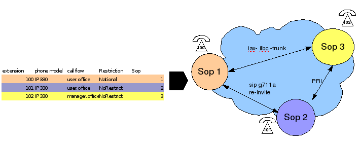
3 different extensions on 3 different SOPs
Cluster configuration
When the consolidated management option is activated, an additional Cluster Level is added to the SOP network overview page. For example, the following drawing illustrates a configuration of a central site (site-a) configured with High Availability and 3 other sites each hosting a SOP. The 5 physical SOPs are configured through a single Cluster Manager. The Cluster Manager is just a virtual representation of the cluster as a whole and not a physical machine.
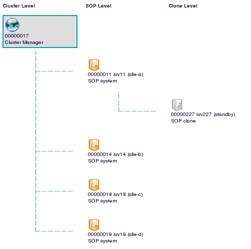
4 autonomous sites managed by a single SOP cluster
In such a configuration, the management can be done at Cluster, SOP and Clone level.
The following menu items are available on the Cluster level:
- Directory
- Callflow studio
- Call Routing
- Intra-cluster routing
- Route Groups
- Restriction Groups
- External Number mapping (incoming and outgoing)
- Resources
- Reporting
- Advanced Reporting
- Time slot definition
- Price list
- Advanced
- Action Management
- Configuration Management
- System Tasks
The following menu items are available on the SOP level:
- Directory
- Internal Directory (only for extensions defined on the master physical SOP)
- Call Routing
- Resources (only for resources defined on the master physical SOP)
- Reporting
- Advanced
- Server Configuration
- Module Configuration
- Configuration Management
- System Status
- System Tasks
The following menu items are available on the Clone level:
You can navigate to the Cluster Manager by clicking the world icon:

Cluster Manager icon
The SOP network map can be requested by clicking on the tree icon:

SOP network map icon
Cluster Manager configuration
The configuration of a Cluster Manager is similar to a single SOP except for the following:
- there is an additional page for configuring the intra-cluster routing
- the internal directory has an additional
SOP property indicating on which physical SOP the extension resides (home SOP)
- each phone has an additional
SOP property indicating on which physical SOP the phone will register
- the following constraints apply:
- the SOP of the primary and secondary phone must match the SOP of the extension
- a queue can only contain phones that are located on the same SOP
Intra-cluster routing
Intra-cluster routing is the mechanism to specify how individual extensions are routed within the cluster. The idea is to start by defining a full mesh of connections between all SOPs and then optimize the routing by adding more specifc routes.
In order to facilitate the meshed network implementation, the concept of a
mesh route has been introduced. A mesh route is an interface configured on all SOPs pointing to a specific SOP (e.g. SOA2 for a SIP mesh trunk).
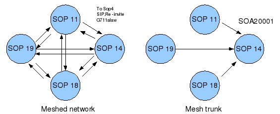
SOP Meshed network
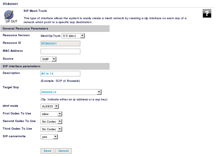
SIP Mesh Trunk Definition
See GenResourceReferenceGuide#MeshSipTrunk_SOA2_v1_00 for more information
To configure the intra-cluster routing:
- Create a SIP mesh trunk with the required parameters pointing towards each SOP
- Navigate to Call Routing > Intra-cluster routing
- Define specific, default and mesh routes as indicated in the legend:
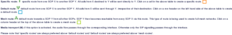
Specific, default and mesh routes
- Each SOP must be connected to each other:
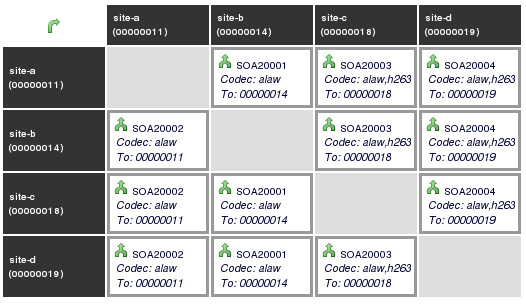
Intra-cluster routing
Per SOP configuration
Following things remain to be done for each SOP separately:
- SOP server and module configuration
- Extra Cluster Routing (legacy routing):
- Dial plan can vary from one SOP to another taking into account national dial plan. As a result, each route group can have a different implementation from one SOP to another
For example: the 'Mobile route group' can be different in US and in Belgium
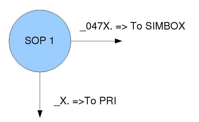
Extra-cluster routing for the illustrating the routing of mobile destination to a SIMBOX.
Checklist for Consolidated Management configuration
- Directory entries must have the
SOP set in order to attach them to a specific (home) SOP
- Some types of resources can be:
- Configured on a single SOP: E.g. ZOA10001 (Native PRI interface), Phones, ...
- Configured on all SOPs: E.g. SOA20001 (Mesh SIP trunk), ...
- Either configured on a single or on all SOPs: E.g. SDA10001 (Wireless Phones), ...
- Resource names must be unique for the whole cluster
- Extra-cluster routing can use mesh trunks to facilitate the routing table
- Prompts and Music-on-hold must be uploaded on each SOP
- Queues < 1.8 are defined on all SOPs. Example: a 'support' queue, when defined will be available on all SOPs (in fact all SOPs will have a queue named "support" but it will not be the same queue) but a queue on SOP A can only contain phones located on SOP A. Queues >= 2.0 are only defined on selected SOPs.
- The STARTDYNAMICAPPLICATION.4.00+ application selector must be used to route calls taking into account the intra-cluster routing.
- The STARTAPPLICATION application selector can be used to simply call a local implementation (for example with a local queue) of a callflow.
- a new GetExtensionInfo action allows to get the home SOP of a specific extension. It is then possible to use CallInterface with a mesh trunk to call a specific application on the home SOP.
- When a call enters via an interface and is routed to the internal context, the MapDDI action is called to map the external number to an internal number. It is only at this point and by using the STARTAPPLICCATION.4.00 (or above) application selector that the intra-cluster routing will be applied.
- Pickup Groups are defined per SOP.
- It is advised to always configure internal directory and resources at the Cluster Manager level.
Speeding up Apply Changes on large installations
On a cluster with many SOPs and many extensions/resources, a full "Apply Cluster Changes" can take a considerable time to complete. If this is a problem, a number of possibilities exist to avoid this:
- Apply SOP Changes: From the SOP view you can do "Apply SOP Changes". This will only run the apply changes on one SOP instead of all. This can be used if the change only affects one SOP. Examples are changes in phone resources, physical interfaces and extra-cluster routes. Also changes in callflows if they are only used on one SOP.
- Apply Extension Change: In the internal directory, press the "Apply Extension Change" icon to apply the changes for one extension. Note that changes to an extension will be replicated to all SOPs in the Cluster. You cannot use Apply SOP Changes for extensions. See Section 3.3 Move, Add, Change and ExtensionMoveAddChange.
- Apply Callflow Change: In the callflow editor, use the "Apply Callflow Changes" to apply just the changes made to that callflow. The change in done on all SOPs in the cluster. See Apply Callflow Changes Administrator Guide.
SOPShell
Introduction
The SOP Shell enables you to test some important features of your SOP.
The SOP Shell can be accessed by one of the following means:
- Attach a screen and keyboard to the SOP server
- Connect via ssh to the SOP server (the IP address as given in the server configuration)
In both cases login as 'admin' (the default password is also 'admin')
Some functions in the SOP Shell are only available if the corresponding module is installed (E.g. the menu entry 'High Availabililty' is only available if the high-availability module is installed)
Test connectivity to SMP
If the SMP indicates that it doesn't have connectivity to your SOP, you can use Diagnostics > SMP Connection. This will run a series of tests. If any of these tests fail, see below for hints on what to do.
checking if eth0 is connected...NOT OK
- Check that the LAN cable is connected to your switch
pinging default gateway...NOT OK
- Check the SOP network config.
- This may fail if your default gateway is e.g. a firewall that doesn't reply to pings. In that case ignore the error.
checking if SOPKEY is set...NOT OK
- The SOP wasn't properly installed, try setting the SOPKEY (Configuration menu)
checking if outbound DNS works...NOT OK
- Check the DNS servers in the SOP network config
- Check your firewall that it allows outgoing DNS requests
- If this fails, the SOP will still be able to connect to the SMP but some functions won't work (e.g. voicemail to email, NTP synchronization, ...)
checking if outbound HTTP to smp-boot.escaux.com works...NOT OK
- Check your firewall or router, it must allow outgoing HTTP without proxy.
trying to obtain ssh connect details...NOT OK
- you have (incorrectly) changed your SOPKEY.
- there is a temporary failure on the SMP
- your SOP may not correctly provisioned on the SMP.
testing outbound TCP to 213.246.219.79:22...NOT OK
- Check your firewall or router, it must allow outgoing SSH (TCP port 22).
testing SSH authentication...NOT OK
- there is a temporary failure on the SMP
- your SOP may not correctly provisioned on the SMP.
Note that this only checks that the SOP should be capable of making a connection with the SMP. It doesn't check if the connection with SMP is actually established! For that use "Subsystems > SMP Connection > View Log A". If you see the following the connection is established:
Pseudo-terminal will not be allocated because stdin is not a terminal.
If the connection to the SMP really does not work, the customer could temporarily establish a static port forwarding on its firewall to debug this.
(For redundancy, there are two connections to the SMP (A and B). It suffices that any the two is established.)
Shutdown and restart the SOP
If needed, you can stop the SOP by using the SOP Shell:
- menu "System" - "Shutdown"
- Attention : All telephony communications passing through the SOP will end
- Wait about 1 minute for the server to shutdown.
- To start the SOP after a shutdown, press the power button.
Never power off the SOP without using the Shutdown function!
To simply restart the SOP:
- menu "System" - "Reboot"
- Attention : All telephony communications passing through the SOP will end
- Wait about 5 minutes for the server to be rebooted.
To boot the standby partition:
- menu "System" - "Reboot other Partition"
- select the desired partition
- To switch to the standby partition select the SOP partition other than the current
- Do not choose the Maintenance partition, unless both SOP partitions fail to boot
- Attention : All telephony communications passing through the SOP will end
- Wait about 5 minutes for the server to be rebooted in the other partition.
Restoring network connectivity
In case you lost the connectivity to the SMP because you made an error in the network configuration, you can no longer correct it from the SMP...
To overcome this, you can temporary change the network configuration of the SOP using "Configuration > Network". You can either enter the network config manually (in case you don't have a DHCP server) or just let the SOP obtain the network config automatically from DHCP.
After the connectivity with the SMP is restored you should correct the network settings on the SMP and reinstall the Network Module ! Otherwise most functionality (including telephony) may not work.
Ping
You may use the SOP-shell to ping some IP addresses and to check that there is :
- no packet loss
- not a too big jitter (variation in the delay)
This is available through the diagnostics menu / network / ping
SMP Accounting
Introduction
While using the SMP web interface, a log is kept of all the actions that may affect your configuration. This includes adding, deleting or updating records but also running tasks etc. Merely browsing the configuration is not logged.
The logs can be consulted by using the
ReportSmpWebAudit report.
Event Description
The table below describes how all actions are being logged. It allows you to interprete every possible log entry, showing to which page and button it relates in the SMP web interface.
The meaning of the columns is:
- Class: The type of object in the configuration on which the action has been performed.
- Instance: The specific record in the configuration on which the action has been performed.
- Action: What kind of action has been performed.
Text typeset
like this is used for literal strings in the log. Text in
italic is to describe a value. E.g.
resource name could be
SDP40001.
| Class |
Action |
Instance |
Description |
task |
run |
reload |
Apply Changes |
task |
run |
Install modules |
Advanced > Modules Configuration > Install Modules |
task |
run |
run_app resource name ... |
Advanced > System Tasks > Run |
task |
add, update, delete |
resource name |
Advanced > System Tasks |
user |
add, update, delete |
user name |
Directory > Users |
extension |
add, update, delete |
extension |
Directory > Internal Directory |
profile |
add, update, delete |
profile name |
Callflow Studio > Profiles |
status |
add, update, delete |
status name |
Callflow Studio > Statuses |
callflow_tech |
add, update, delete |
extension |
Callflow Studio > Callflows, Callflow Technical View |
callflow_assignment |
add, update, delete |
profile . status |
Callflow Studio > Callflow Assignment |
callflow_action |
add, update, delete, delete_branch |
extension |
Callflow Editor |
callflow |
import |
extension |
Callflow Editor > Bulk Admin |
global_param |
add, update, delete |
parameter name |
Callflow Studio > Global Parameters |
global_param |
import |
|
Callflow Studio > Global Parameters > Bulk Admin |
route |
add, update, delete |
extension |
Call Routing > Routes, Extra-Cluster Routing |
context |
add, update, delete |
context name |
Call Routing > Route Groups & Restriction Groups |
context_inclusion |
add, update, delete |
parent context + child context |
Call Routing > Restriction Group Configuration |
ddi |
add, update, delete |
extension |
Call Routing > Incoming Number Mapping |
ddi |
import |
|
Call Routing > Incoming Number Mapping > Bulk Admin |
callerid |
update_all |
|
Call Routing > Outgoing Number Mapping > Save |
callerid |
import |
|
Call Routing > Outgoing Number Mapping > Bulk Admin |
phone |
add, update, delete |
resource name |
Resources > IP Phones |
phone |
import |
|
Resources > IP Phones > Bulk Admin |
interface |
add, update, delete |
resource name |
Resources > Interfaces |
interface |
import |
|
Resources > Interfaces > Bulk Admin |
mle |
add, update, delete |
resource name |
Resources > Media Links |
mle |
import |
|
Resources > Media Links > Bulk Admin |
moh |
add, update, delete |
resource name |
Resources > Music On Hold > Resource Manager |
moh |
import |
|
Resources > Music On Hold > Resource Manager > Bulk Admin |
queue |
add, update, delete |
resource name |
Resources > Queues |
queue |
import |
|
Resources > Queues > Bulk Admin |
probe |
add, update, delete |
resource name |
Resources > Probes |
probe |
import |
|
Resources > Probes > Bulk Admin |
client |
add, update, delete |
resource name |
Resources > Desktop Applications |
client |
import |
|
Resources > Desktop Applications > Bulk Admin |
permission |
add, update, delete |
user name + resource name |
Resources > Permissions |
permission |
import |
|
Resources > Permissions > Bulk Admin |
basic_report |
add, update, delete, view |
report name |
Reporting > Basic Reports |
report |
add, update, delete, view |
resource name |
Reporting > Advanced Reports |
report |
import |
|
Reporting > Advanced Reports > Bulk Admin |
timeslot |
add, update, delete |
timeslot name |
Reporting > Time Slots |
mdl |
add, update, delete |
code prefix |
Reporting > Price List |
mdl |
import |
|
Reporting > Price List > Bulk Admin |
sop |
update, accept_key, clear_key |
|
Advanced > Server Configuration |
module |
add, update, delete, toggle_install, update_version |
module name |
Advanced > Modules Configuration |
action |
update_version |
action name + new version |
Advanced > Action Management |
backup |
restore |
file name |
Advanced > Restore Configuration Snapshot |
subsystem |
update_all |
|
Advanced > Subsystem Status > Submit |
subsystem_command |
run |
command name |
Advanced > Subsystem Status > Start/Stop/Restart |
Licenses
Depending of your commercial contract you have rights to use a certain number of resources of each type. For instance if you have purchased 10 phone licenses, you can create up to 10 phone resources.
You can consult the counters by using the "view licenses" link from the respective resources list page:
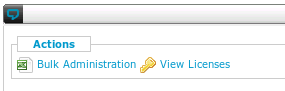
The type of license is identified by the first characters of the resource name.
For example a phone resource
SDP40001 will consume a phone license because a phone license is defined as anything that has a name starting with
SD (SIP Device),
ZD (Zaptel Device),
ID (IAX Device),
LD (Local Device) or
SV (SIP Virtual).
See below the name of the licenses :
| License name |
Codes |
| net.Phone |
SD/ZD/ID/LD/SV |
| Queue |
AQA |
| Advanced Reporting |
RWC/RWQ/RWD/RWS/RWA |
| net.Supervisor |
WCE0 |
| net.Desktop X100 |
WCE1 |
| net.Desktop X300 |
WCE3 |
| net.Desktop X350 |
WCE4 |
| net.Desktop X500 |
WCE5 |
| net.Console X700 |
WCE7 |
| net.Console X900 |
WCE9 |
Network configuration
Firewall configuration
Firewall configuration
- Administration Guide: Unified Communication Solution 4.8
- Preface
- Introduction
- SMP configuration and menus
- Use cases and scenarios
- Setting a maximum call duration
- Prompt recording callflow
- Creating an IVR
- Pickup system
- Directed call pickup
- Status browsing callflow
- Directed call parking
- Introduction
- Implementation
- Preparation, step 1: Directed Call Parking call flow
- Preparation, step 2: Adapting the routing plan in order to create the feature access code
- Directed park retrieve, step 1: Creating the global parameters
- Directed park retrieve, step 2: Importing DirectedParkRetrieve callflow
- Directed park retrieve, step 3: Creating DirectedParkRetrieve profile
- Directed park retrieve, step 4: Assigning the callflow
- Directed park retrieve, step 5: Creating the service extension
- Directed park retrieve, step 6: Configuring service profile
- Directed park retrieve, step 7: adding a route for prefix *55
- Directed park retrieve, step 8: sending the call to the DirectedParkRetrieve service
- Usage and examples
- DTMF based call transfer
- Mobility login and logout callflow
- Caller ID manipulation for outgoing calls
- Extended huntgroups
- Bulk administration
- Replacing a (broken) SOP
- Advanced configuration topics
- Network configuration
- References
Introduction
SOP connectivity
Standard firewall configuration
When your
SOP is operational, it will contact the
SMP by using your internet connection for a number of reasons. This requires opening up some ports on your firewall from the inside (LAN) to the outside (internet).
It is likely however that you don't have to change anything on your firewall. Most firewall configurations allow all traffic from the LAN to the internet.
In case of a high availability setup (active-standby or active-active) all the IP addresses used by the SOPs must be permitted.
The following firewall configuration is required:
| From |
To |
Protocol |
Port |
Explanation |
| SOP |
* |
TCP |
SSH (22) |
Used for authenticated and encrypted management of the SOP |
| SOP |
* |
TCP |
HTTP (80) |
Used to query which SMP the SOP should use. |
| SOP |
* |
TCP |
HTTPS (443) |
Software and security updates for the SOP. |
| SOP |
Customer's SMTP server |
TCP |
SMTP (25) |
Used for voicemail-to-email |
| SOP |
* |
UDP |
NTP (123) |
Used for time synchronization |
| SOP |
* |
UDP |
DNS (53) |
Used to convert hostnames to IP addresses |
| Management network |
SOP |
TCP |
HTTP (80) |
Manage audio prompts, music on hold files and call recordings |
| Management network |
SOP |
TCP |
HTTPS (443) |
Manage audio prompts, music on hold files and call recordings |
HTTP connectivity proxied through your corporate proxy server is NOT supported.
MTU (Maximum Transmission Unit) should be 1500 bytes or higher.
Strict firewall configuration
The strict firewall configuration is suitable for customers where the recommended firewall configuration is not possible due to their security policy. In comparison with the recommended firewall configuration, the strict firewall configuration has additional restrictions on outgoing connections.
Please note that the current IP ranges 213.246.219.64/27 & 213.246.255.232/29 & 217.111.215.88/29 & 188.118.34.80/32 & 188.118.34.81/32 & 188.118.34.120/32 & 188.118.34.121/32 could change or that IP ranges might be added or removed in the future. You will be informed if and when this happens and will need to change your firewall configuration.
| From |
To |
Protocol |
Port |
Explanation |
| SOP |
213.246.219.64/27 & 213.246.255.232/29 & 217.111.215.88/29 & 188.118.34.80/32 & 188.118.34.81/32 & 188.118.34.120/32 & 188.118.34.121/32 |
TCP |
SSH (22) |
Used for authenticated and encrypted management of the SOP |
| SOP |
213.246.219.64/27 & 213.246.255.232/29 & 217.111.215.88/29 & 188.118.34.80/32 & 188.118.34.81/32 & 188.118.34.120/32 & 188.118.34.121/32 |
TCP |
HTTP (80) |
Used to query which SMP the SOP should use. |
| SOP |
213.246.219.64/27 & 213.246.255.232/29 & 217.111.215.88/29 & 188.118.34.80/32 & 188.118.34.81/32 & 188.118.34.120/32 & 188.118.34.121/32 |
TCP |
HTTPS (443) |
Software and security updates for the SOP. |
| SOP |
Customer's SMTP server |
TCP |
SMTP (25) |
Used for voicemail-to-email |
| SOP |
Customer's NTP server(s) |
UDP |
NTP (123) |
Used for time synchronization |
| SOP |
Customer's DNS server(s) |
UDP |
DNS (53) |
Used to convert hostnames to IP addresses |
| Management network |
SOP |
TCP |
HTTPS (443) |
Manage audio prompts, music on hold files and call recordings |
| Management network |
SOP |
TCP |
HTTP (80) |
Manage audio prompts, music on hold files and call recordings |
HTTP connectivity proxied through your corporate proxy server is NOT supported.
MTU (Maximum Transmission Unit) should be 1500 bytes or higher.
SIP trunk connectivity to a telecom operator
| From |
To |
Protocol |
Port |
Explanation |
| SOP |
Provider's SIP proxy server |
UDP |
SIP (5060) |
Used for SIP Protocol |
| Provider's SIP proxy server |
SOP |
UDP |
SIP (5060) |
Used for SIP Protocol |
| SOP |
Provider's media gateway |
UDP |
1024-65535 |
Used for RTP media traffic (1) |
| Provider's media gateway |
SOP |
UDP |
1024-65535 |
Used for RTP media traffic |
(1) this range can be modified according to the SIP provider's requirements.
Network Address Translation is not supported.
Please consult our
Security recommendation guide before implementing firewall changes.
Inter-SOP connectivity (clustering + active / active)
| Protocol |
Port |
Explanation |
| TCP |
SSH (22) |
Cluster synchronisation (prompts, music-on-hold files) |
| UDP |
SIP (5060) |
Mesh SIP trunks |
| UDP |
10000-20000 |
RTP voice traffic |
| TCP |
HTTP (80) |
Inter-sop API requests |
| TCP |
HTTPS (443) |
Inter-sop API requests |
| TCP |
4445 |
Application management server sync (phone statuses, profile parameters,...) |
There is no specific requirements for an active-active setup.
Network Address Translation is not supported.
SMP Phone status & reboot
| Phones |
Web Interface
User PC -> Phones |
Reboot feature
SOP -> Phones |
| Brands |
Prefix |
Protocol |
Port |
Protocol |
Port |
| Aastra |
SDR |
HTTP |
80 |
HTTP |
80 |
| Budgetone |
SDB |
- |
- |
- |
- |
| Cisco |
SDC |
HTTP |
80 |
HTTP |
80 |
| Cisco |
SDS |
HTTP |
80 |
HTTP |
80 |
| Grandstream |
SDG3 |
HTTP |
80 |
HTTP |
80 |
| Hitachi |
SDA |
- |
- |
- |
- |
| Mitel |
SDM |
HTTP |
80 |
SIP |
5060 |
| Polycom |
SDP |
HTTP |
80 |
SIP |
5060 |
| Snom |
SDO1-7 |
HTTP |
80 |
SIP |
5060 |
| Swiss Voice |
SDW |
- |
- |
- |
- |
| Thomson |
SDT |
- |
- |
- |
- |
| Unidata |
SDU |
HTTP |
8080 |
- |
- |
' - ' Reboot and access to web interface aren't supported.
Escaux Connect for UEP 1.1
- A domain name
- A valid certificate for the domain
| From |
To |
Protocol |
Port |
| Internet |
ISAP |
TCP |
HTTP (80) |
| Internet |
ISAP |
TCP |
HTTPS (443) |
| Internet |
ISAP |
TCP |
WebSocket (8088) |
| UEP |
WebRTC |
UDP |
SIP (5060) |
| WebRTC |
UEP |
UDP |
SIP (5060) |
| UEP |
WebRTC |
UDP |
RTP (10000-20000) |
| WebRTC |
UEP |
UDP |
RTP (10000-20000) |
| PBX |
UEP |
TCP |
HTTP (80) |
| PBX |
UEP |
TCP |
SIP (5060) |
| PBX |
UEP |
TCP |
RTP (10000-20000) |
Connect Me
This application was formally known as Escaux Connect or Fuzer Connect.
Client
Recommended
For basic functionality:
| From |
To |
Protocol |
Port |
Comment |
| Client |
Customer's DNS server |
UDP |
53 (DNS) |
|
| Client |
Internet |
TCP |
80 (HTTP) |
Optional : Only used to redirect to HTTPS |
| Client |
Internet |
TCP |
443 (HTTPS) |
|
For softphone functionality:
| From |
To |
Protocol |
Port |
Comment |
| Client |
The IP range is dependent on your deployment |
UDP |
The port range is dependent on your deployment |
Only for UEP on customer premises |
| Client |
* |
UDP |
All high ports: 1024-65535 (RTP) |
Cloud based customers |
For mediabridge direct media (point-to-point video & screen sharing):
| From |
To |
Protocol |
Port |
| Client |
* |
UDP |
All high ports: 1024-65535 (RTP) |
For mediabridge relayed media (point-to-point video & screen sharing via TURN server):
| From |
To |
Protocol |
Port |
| Client |
Internet |
UDP |
49152-65535 (TURN relay) |
| Client |
Internet |
UDP |
3478 (TURN) |
| Client |
Internet |
TCP |
5349 (TURN over TLS) |
Strict
The strict firewall configuration is suitable for customers where the recommended firewall configuration is not possible due their security policy. In comparison with the recommended firewall configuration, the strict firewall configuration has additional restrictions on outgoing connections.
Please note that the current IP ranges 213.246.219.64/27 & 213.246.255.232/29 & 217.111.215.88/29 & 188.118.34.80/32 & 188.118.34.81/32 & 188.118.34.120/32 & 188.118.34.121/32 could change or that IP ranges might be added or removed in the future. You will be informed if and when this happens and will need to change your firewall configuration.
For basic functionality:
| From |
To |
Protocol |
Port |
Comment |
| Client |
Customer's DNS server |
UDP |
53 (DNS) |
|
| Client |
213.246.219.64/27 & 213.246.255.232/29 & 217.111.215.88/29 & 188.118.34.80/32 & 188.118.34.81/32 & 188.118.34.120/32 & 188.118.34.121/32 |
TCP |
80 (HTTP) |
Optional : Only used to redirect to HTTPS |
| Client |
213.246.219.64/27 & 213.246.255.232/29 & 217.111.215.88/29 & 188.118.34.80/32 & 188.118.34.81/32 & 188.118.34.120/32 & 188.118.34.121/32 |
TCP |
443 (HTTPS) |
|
For softphone functionality:
| From |
To |
Protocol |
Port |
Comment |
| Client |
The IP range is dependent on your deployment |
UDP |
The port range is dependent on your deployment |
Only for UEP on customer premises |
| Client |
213.246.219.64/27 & 213.246.255.232/29 & 217.111.215.88/29 & 188.118.34.80/32 & 188.118.34.81/32 & 188.118.34.120/32 & 188.118.34.121/32 |
UDP |
All high ports: 1024-65535 (RTP) |
Cloud based customers |
For mediabridge direct media (point-to-point video & screen sharing):
| From |
To |
Protocol |
Port |
| Client |
* |
UDP |
All high ports: 1024-65535 (RTP) |
For mediabridge relayed media (point-to-point video & screen sharing via TURN server):
| From |
To |
Protocol |
Port |
| Client |
Internet |
UDP |
49152-65535 (TURN relay) |
| Client |
Internet |
UDP |
3478 (TURN) |
| Client |
Internet |
TCP |
5349 (TURN over TLS) |
Server
Eth0
| From |
To |
Protocol |
Port |
Comment |
| ISAP |
OAuth |
TCP |
7380 |
oAuth requests |
Eth0 (backend - Escaux)
| From |
To |
Protocol |
Port |
| CDG |
All FMU |
UDP |
SIP 5060 |
| All FMU |
CDG |
UDP |
SIP 5060 |
| CDG |
All FMU |
UDP |
RTP range 10000 - 20000 |
| CDG |
LS |
UDP |
SIP 5060 |
| LS |
CDG |
UDP |
SIP 5060 |
| CDG |
CAG |
UDP |
SIP 5060 |
| CAG |
CDG |
UDP |
SIP 5060 |
| CDG |
|
|
Standard SOP connectivity |
With HLR connectivity:
| From |
To |
Protocol |
Port |
| CDG |
CAG |
UDP |
SIP 5060 |
| CAG |
CDG |
UDP |
SIP 5060 |
Eth1 (provider)
If the connection with the provider is not SIP but ISUP, this section is irrelevant.
Minimum rules on Escaux interface:
| From |
To |
Protocol |
Port |
| CAG |
All FMU |
UDP |
SIP 5060 |
| All FMU |
CAG |
UDP |
SIP 5060 |
| CAG |
LS |
UDP |
SIP 5060 |
| LS |
CAG |
UDP |
SIP 5060 |
| CAG |
CDG |
UDP |
SIP 5060 |
| CDG |
CAG |
UDP |
SIP 5060 |
| CAG |
|
|
Standard SOP connectivity |
With HLR connectivity:
| From |
To |
Protocol |
Port |
| CAG |
CDG |
UDP |
SIP 5060 |
| CDG |
CAG |
UDP |
SIP 5060 |
SIGTRAN link with provider:
SCTP not yet managed by the firewall.
SIP link with provider: on the provider interface:
| From |
To |
Protocol |
Port |
| CAG |
MSS |
UDP |
SIP 5060 |
| MSS |
CAG |
UDP |
SIP 5060 |
| From |
To |
Protocol |
Port |
| LS |
CAG |
UDP |
SIP 5060 |
| CAG |
LS |
UDP |
SIP 5060 |
| LS |
CDG |
UDP |
SIP 5060 |
| CDG |
LS |
UDP |
SIP 5060 |
| LS |
|
|
Standard SOP connectivity |
| From |
To |
Protocol |
Port |
| Internet |
ISAP |
TCP |
HTTP (80) |
| Internet |
ISAP |
TCP |
HTTPS (443) |
| Internet |
ISAP |
TCP |
SSH (22) |
| ISAP |
UEP |
TCP |
HTTP 80 (CardDAV) |
| ISAP |
UEP |
TCP |
HTTP 7080 (Connect Me) |
| ISAP |
UEP |
TCP |
HTTP 8080 (UEP API) |
| ISAP |
UEP |
TCP |
HTTP 9080 (Authentication API) |
| ISAP |
File Depot |
TCP |
HTTP 5080 (File Depot API) |
| ISAP |
WebRTC |
TCP |
HTTP 2080 (WebRTC API) |
| ISAP |
WebRTC |
TCP |
WebSocket 8088 (SIP over Websocket) |
| ISAP |
|
|
Standard SOP connectivity |
WebRTC
| From |
To |
Protocol |
Port |
| Internet |
WebRTC |
UDP |
RTP port range 10000-20000 (NATed by the firewall). Other ranges can be used. |
| WebRTC |
Internet |
UDP |
RTP port range 10000-20000 (NATed by the firewall). Other ranges can be used. |
| WebRTC |
UEP |
UDP |
SIP 5060 |
| UEP |
WebRTC |
UDP |
SIP 5060 |
| WebRTC |
UEP |
UDP |
RTP range (10000-20000) |
| WebRTC |
UEP |
TCP |
HTTP 8000 |
| WebRTC |
|
|
Standard SOP connectivity |
| From |
To |
Protocol |
Port |
| GCM (FCM) |
UEP |
UDP |
SIP port 5060 |
| UEP |
GCM (FCM) |
UDP |
SIP port 5060 |
| GCM (FCM) |
UEP |
TCP |
HTTP port 8000 (UEP-API) |
| GCM (FCM) |
ISAP |
TCP |
SSH port 22 |
| ISAP |
GCM (FCM) |
TCP |
HTTP port 2080 (FCM-API) |
| GCM (FCM) |
Internet |
TCP |
HTTPS port 443 |
| GCM (FCM) |
|
|
Standard SOP connectivity |
Three different FMU modes are considered here:
- standalone mode (FMU directly connected to the customer (UEP))
- gateway mode 1 interface (when the UEP is in the Escaux solution)
- gateway mode 2 interfaces (when the UEP is on the client => FMU plays the role of the border route).
Standalone mode: with this mode FMU is directly connected to the customer (no UEP)
2 interfaces are necessary because its a border router: one for the customer (eth0) and the second for Escaux side (eth1)
Eth0 (customer):
| From |
To |
Protocol |
Port |
| FMU |
PABX |
UDP |
SIP port 5060 to 9061 |
| PABX |
FMU |
UDP |
SIP port 5060 to 9061 |
| FMU |
PABX |
UDP |
RTP ranges (10000-20000) |
| FMU primary |
FMU failover |
UDP |
SIP port 5060 |
| FMU failover |
FMU primary |
UDP |
SIP port 5060 |
Eth1 (Escaux - management):
| From |
To |
Protocol |
Port |
| FMU |
CDG |
UDP |
SIP port 5060 |
| CDG |
FMU |
UDP |
SIP port 5060 |
| FMU |
CDG |
UDP |
RTP ranges (10000-20000) |
| FMU |
CAG |
UDP |
SIP port 5060 |
| CAG |
FMU |
UDP |
SIP port 5060 |
| FMU primary |
FMU failover |
UDP |
SIP port 5060 |
| FMU failover |
FMU primary |
UDP |
SIP port 5060 |
| FMU |
|
|
Standard SOP connectivity |
Gateway mode 1 interface: in this case there is only one interface, this mode is used when the UEP is in the Escaux solution (UEP is in the cloud).
| From |
To |
Protocol |
Port |
| FMU |
UEP |
UDP |
SIP port 5060 and 5061 |
| UEP |
FMU |
UDP |
SIP port 5060 and 5061 |
| FMU |
UEP |
UDP |
RTP ranges (10000-20000) |
| FMU |
CDG |
UDP |
SIP port 5060 |
| CDG |
FMU |
UDP |
SIP port 5060 |
| FMU |
CDG |
UDP |
RTP ranges (10000-20000) |
| FMU |
CAG |
UDP |
SIP port 5060 |
| CAG |
FMU |
UDP |
SIP port 5060 |
| FMU primary |
FMU failover |
UDP |
SIP port 5060 |
| FMU failover |
FMU primary |
UDP |
SIP port 5060 |
| FMU |
|
|
Standard SOP connectivity |
Gateway mode 2 interfaces : this mode is used when the UEP is on the client and the FMU plays the role of the border router.
Eth0 (client)
| From |
To |
Protocol |
Port |
| FMU |
UEP |
UDP |
SIP port 5060 and 5061 |
| UEP |
FMU |
UDP |
SIP port 5060 and 5061 |
| FMU primary |
FMU failover |
UDP |
SIP port 5060 |
| FMU failover |
FMU primary |
UDP |
SIP port 5060 |
| FMU |
UEP |
UDP |
RTP ranges (10000-20000) |
Eth1 (Escaux Management)
| From |
To |
Protocol |
Port |
| FMU |
CDG |
UDP |
SIP port 5060 |
| CDG |
FMU |
UDP |
SIP port 5060 |
| FMU |
CDG |
UDP |
RTP ranges (10000-20000) |
| FMU |
CAG |
UDP |
SIP port 5060 |
| CAG |
FMU |
UDP |
SIP port 5060 |
| FMU primary |
FMU failover |
UDP |
SIP port 5060 |
| FMU failover |
FMU primary |
UDP |
SIP port 5060 |
| FMU |
|
|
Standard SOP connectivity |
| From |
To |
Protocol |
Port |
| UEP |
Gateways (WebRTC/APN/GCM/FMU) |
UDP |
SIP port 5060 |
| Gateways (WebRTC/APN/GCM/FMU) |
UEP |
UDP |
SIP port 5060 |
| UEP |
Gateways (WebRTC/APN/GCM/FMU) |
UDP |
RTP ranges (10000-20000) |
| UEP |
PABX |
UDP |
SIP port 5060 |
| UEP |
PABX |
UDP |
RTP ranges (10000-20000) |
| UEP |
PABX |
TCP |
HTTP port 80 |
| UEP |
SMP-Web* |
TCP |
HTTPS port 443 |
| UEP |
|
|
Standard SOP connectivity |
User agent - SOP
net.Desktop connectivity
If the users have the net.Desktop application running on their computer and a firewall is present between the users' LAN and the SOP, the following firewall configuration is required:
| Protocol |
From |
To |
Destination port(s) |
Explanation |
| TCP |
Client |
SOP |
4445 |
net.Desktop - sop event communication |
| TCP |
Client |
SOP |
4446 |
net.Desktop - sop other communication |
| TCP |
Client |
SOP |
4559 |
Outgoing FAX server communication |
| TCP |
Client |
SOP |
25 |
Outgoing FAX server communication (new since 2.28 when using quick fax) |
| UDP |
Client:5060-5070 |
SOP |
5060 |
SIP net.Desktop User Agent |
| UDP |
Client:5060-5070 |
Client |
5060-5070 |
SIP chat peer to peer |
| UDP |
Client:4569 |
Client |
4569 |
Peer to peer video |
Note that there must be a direct IP route between the net.Desktop clients' IPs for the clients to be able to chat. Therefore, net.Desktop clients will not be able to communicate if
Network Address Translation is used.
net.Console connectivity
| From |
To |
Protocol |
Destination port(s) |
Explanation |
| SOP (1) |
Phone |
TCP |
HTTP (80) |
API requests to phone |
| SOP |
Phone |
UDP |
SIP (5060) |
SIP signaling |
| Phone |
SOP |
SIP |
SIP (5060) |
SIP signaling |
| SOP |
Phone |
UDP |
10000-20000 |
RTP traffic. The port range can be limited through the resource configuration of certain phones |
| Phone |
SOP |
UDP |
10000-20000 |
RTP traffic. The port range can be limited through the resource configuration of certain phones. |
| Client |
SOP |
TCP |
SIP over TCP (3040) |
Control connection |
| SOP (1) |
Client |
TCP |
SIP over TCP (3040) |
Control connection |
(1) For active/standby architectures, consider the active and standby IP addresses
net.Supervisor connectivity
| Protocol |
From |
To |
Destination port(s) |
Explanation |
| TCP |
Client |
SOP |
4445 |
net.Supervisor - sop event communication |
| TCP |
Client |
SOP |
HTTP (80) |
SOP API requests |
Desk phone connectivity
Local phone and local SOP
A connection between a desk phone and a locally hosted SOP should be unfirewalled.
Network Address Translation is not supported.
Polycom phone over internet
Recommended:
| From |
To |
Protocol |
Port |
Explanation |
| Phone |
* |
UDP |
NTP (123) |
Time synchronization |
| Phone |
* |
TCP |
SIP over TLS (The specific port(s) depend on your specific implementation. Please contact your project manager to know which one(s).) |
Used for call signalling |
| Phone |
* |
UDP |
(S)RTP (The specific port(s) depend on your specific implementation. Please contact your project manager to know which one(s).) |
Used for call voice |
| Phone |
* |
UDP |
DNS (53) |
Used to convert hostnames to IP addresses |
| Phone |
* |
TCP |
HTTPS (443) |
Connection towards the Pure Cloud provisioning domain |
Strict:
The strict firewall configuration is suitable for customers where the recommended firewall configuration is not possible due to their security policy. In comparison with the recommended firewall configuration, the strict firewall configuration has additional restrictions on outgoing connections.
Please note that the current IP ranges 213.246.219.64/27 & 213.246.255.232/29 & 217.111.215.88/29 & 188.118.34.80/32 & 188.118.34.81/32 & 188.118.34.120/32 & 188.118.34.121/32 could change or that IP ranges might be added or removed in the future. You will be informed if and when this happens and will need to change your firewall configuration.
| From |
To |
Protocol |
Port |
Explanation |
| Phone |
Customer's NTP server(s) |
UDP |
NTP (123) |
Time synchronization |
| Phone |
213.246.219.64/27 & 213.246.255.232/29 & 217.111.215.88/29 & 188.118.34.80/32 & 188.118.34.81/32 & 188.118.34.120/32 & 188.118.34.121/32 |
TCP |
SIP over TLS (The specific port(s) depend on your specific implementation. Please contact your project manager to know which one(s).) |
Used for call signalling |
| Phone |
213.246.219.64/27 & 213.246.255.232/29 & 217.111.215.88/29 & 188.118.34.80/32 & 188.118.34.81/32 & 188.118.34.120/32 & 188.118.34.121/32 |
UDP |
(S)RTP (The specific port(s) depend on your specific implementation. Please contact your project manager to know which one(s).) |
Used for call voice |
| Phone |
Customer's DNS server(s) |
UDP |
DNS (53) |
Used to convert hostnames to IP addresses |
| Phone |
213.246.219.64/27 & 213.246.255.232/29 & 217.111.215.88/29 & 188.118.34.80/32 & 188.118.34.81/32 & 188.118.34.120/32 & 188.118.34.121/32 |
TCP |
HTTPS (443) |
Connection towards the Pure Cloud provisioning domain |
net.Buzz connectivity
| From |
To |
Protocol |
Port |
Explanation |
| PC client |
SOP |
TCP |
HTTP (80) |
Authentication and provisioning |
| PC client |
SOP |
TCP |
LDAP (389) |
Corporate directory via default LDAP directory (optional) |
| PC client |
Customer's LDAP server |
TCP |
LDAP (389) |
Corporate directory via customer LDAP directory (optional) |
| PC client |
SOP |
UDP |
SIP (5060) |
SIP control channel |
| PC client |
secure.counterpath.com (alternatively but not recommended, 69.90.51.170 & 216.93.246.170 & 137.135.52.175 ) |
TCP |
HTTPS (443) |
Licensing server |
| SOP |
PC Client |
UDP |
SIP (5060) |
SIP control channel |
| PC client |
SOP |
UDP |
RTP (port range 30000-31000 by default) |
RTP traffic |
| SOP |
PC client |
UDP |
RTP (port range 10000-20000 by default) |
RTP traffic |
Network Address Translation is not supported.
Counterpath Eyebeam & Bria connectivity
See the firewall requirements for net.Buzz
DHCP configuration
Please have a look
here
VLAN Connections
Switch configuration
The Escaux UCS server must be connected to a switch port which is configured in Voice VLAN only mode.
IP phones
- The first time the IP phones are connected, they should be plugged in a port on the switch that is configured in Voice VLAN only mode. They'll get their initial configuration, with their VLAN ID. Important remarks :
- The VLAN Id should not be defined on the phone in any of the 2 situations below:
- the switch and the phone are both from Cisco -> they use CDP
- the phone will be connected to a port configured in Voice VLAN only mode (i.e. no PC will be connected behind the phone)
- Polycom phones : VLAN Id needs to be defined manually at the first boot (More info here. This means they need to be directly connected to a switch port configured in "trunk" mode (Voice VLAN + Data VLAN).
- Once VLAN ID is configured, phones need to be plugged in a switch port configured in "trunk" mode (Voice VLAN + Data VLAN).
Cisco Discovery Protocol (CDP)
If Cisco switches are used but phones are not Cisco phones, then the customer must desactivate CDP on the switches.
References
- Resource Reference Guide: EN
- Action Reference Guide: EN
- Module Reference Guide: EN
- Audio Prompt Reference Guide: EN
- Global Parameter Reference Guide: EN
- Application Programmer Interface Reference Guide EN